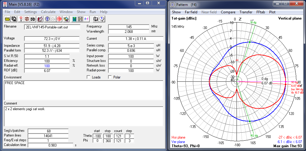
If you liked the 3 elements yagi, this antenna build is very close to the performance of that antenna. This VHF antenna is for 144Mhz with 10Mhz bandwith from 140Mhz to 150Mhz. The antenna measurements are computed and then simulated on 4Nec2 antenna modelling software.
Materials
1×1/2″ rectangular aluminum tubing for the boom
1/2″ aluminum tubing for the elements holder cut in half
3/8″ aluminum tubing for the antenna elements
1pc SO239 connector
Pop rivets / Rivet tool
#10 or #12 AWG copper wire with insulation for the gamma insert
3.5cm 3/8″ aluminum tube for the gamma tube
1 Butteryfly nut and 1bolt 18mm length 3mm diameter
4pcs Stainless steel nuts and bolts 20mm length 3mm diameter
Aluminum plate 0.5mm thickness for the tuning stun
Collapsible tubes different sizes.
U bolt with mounting for the antenna mount
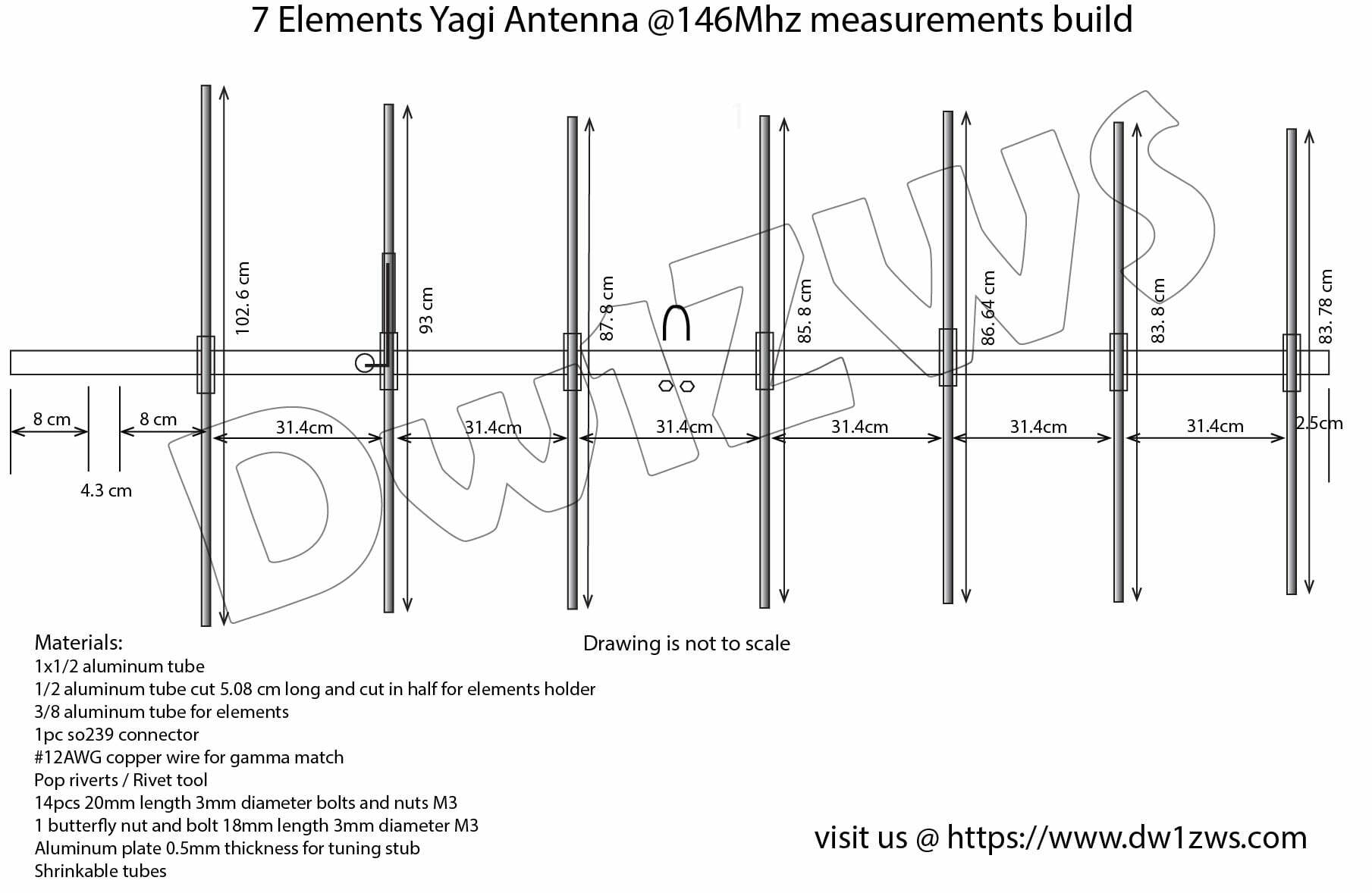
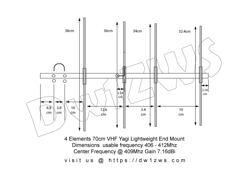
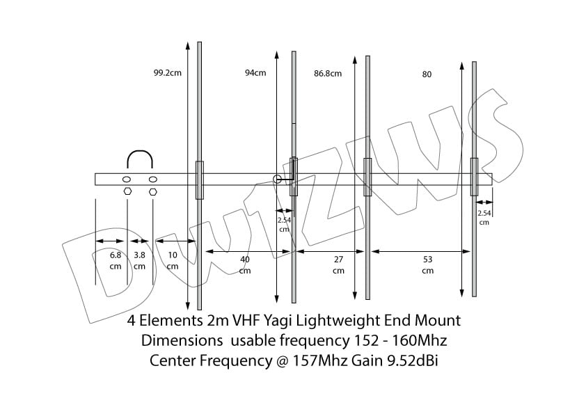
Construction
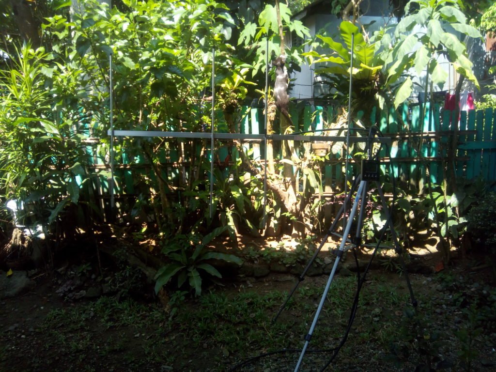
The antenna measurements is provided here for reference. Building it is straightforward you just need to follow the diagram and assemble your contraption. If in doubt you may watch the DIY video of me building a 3 elements yagi without power tools except for the drill.
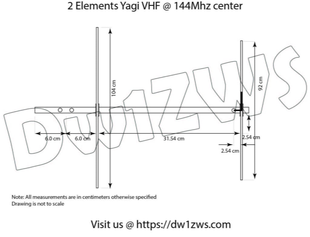
Antenna measurements in PDF format is downloadable here.
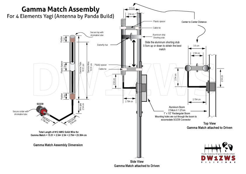
Matching System
I usually used a gamma match for my build, there is nothing special about this impedance matching system but since I’m using a grounded design, (grounded elements to boom) this is I think, the most logical impedance matching system to use, but that is just on me. The reason behind is that the boom is on the zero potential during transition period between the sinusoidal signal therefore elements can be grounded on the boom. In practice there isn’t a noticeable difference between the performance of a grounded elements and an isolated one (debatable). The caveats yagi’s driven element, should be isolated from the boom when using a different matching system. When using a gamma match the center conductor is just capacitively coupled to the driven element via the tuning stub, so it is not electrically grounded.
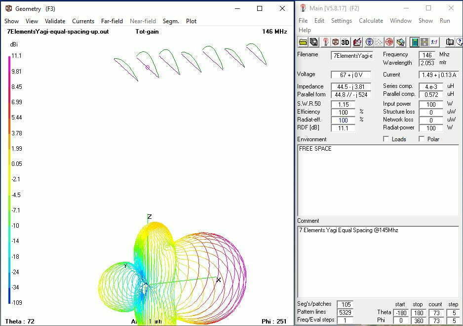
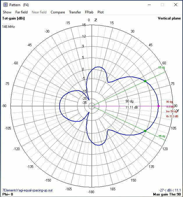
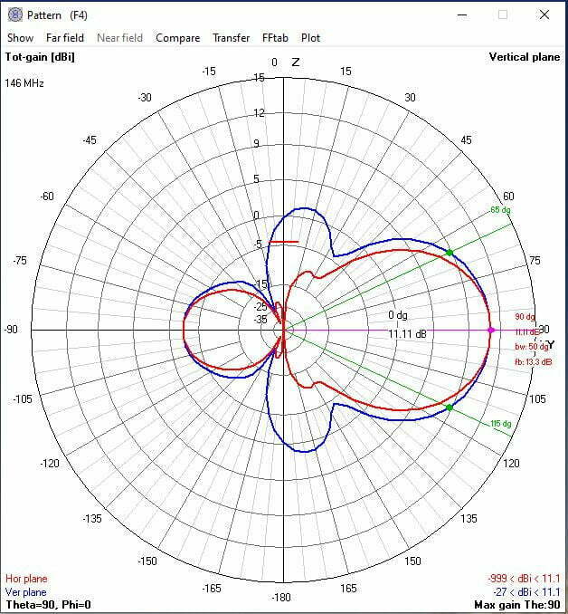
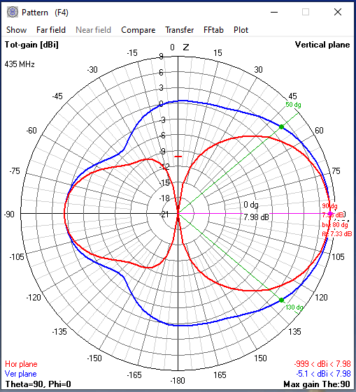
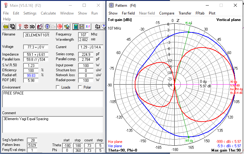
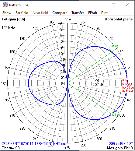
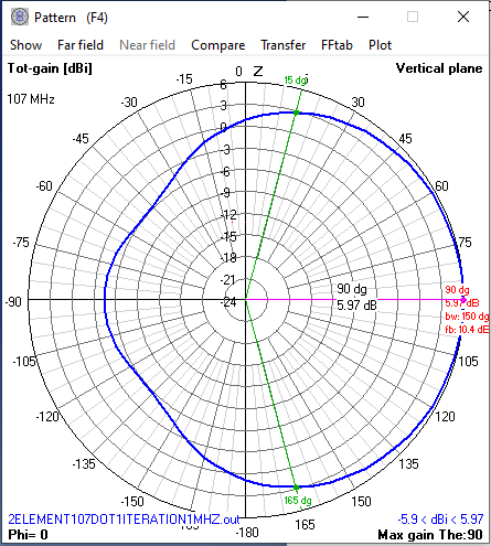
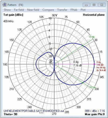
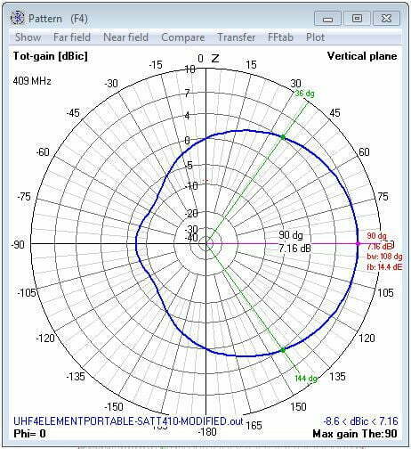
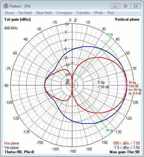
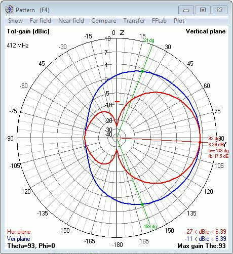
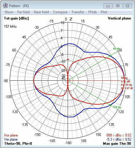
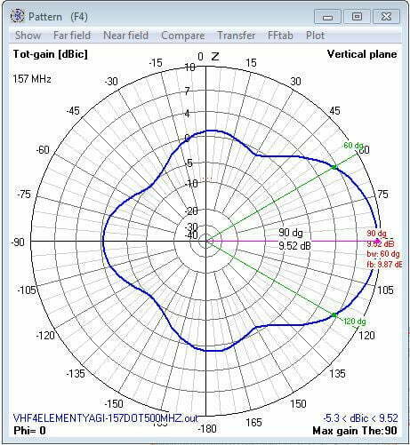
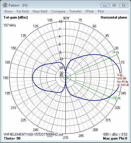
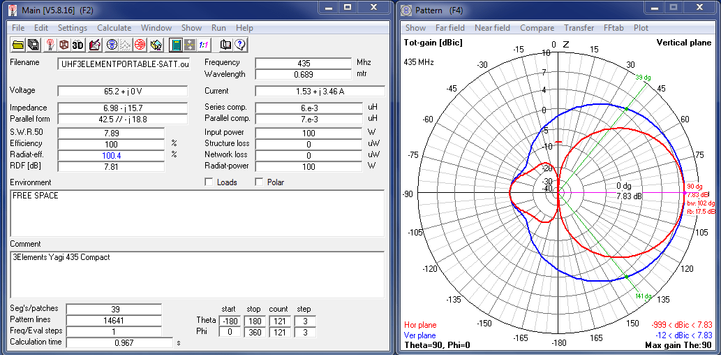
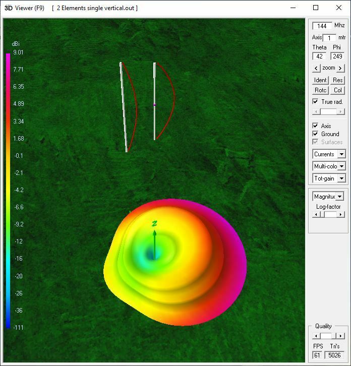
4Nec2 Data
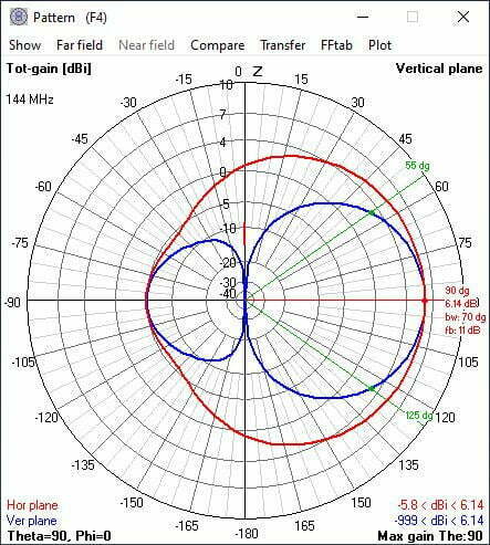
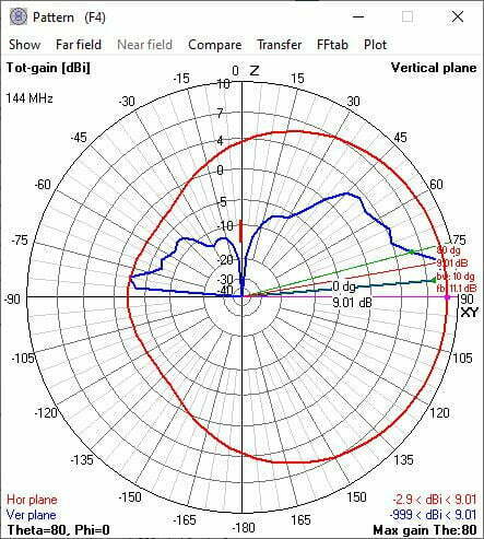
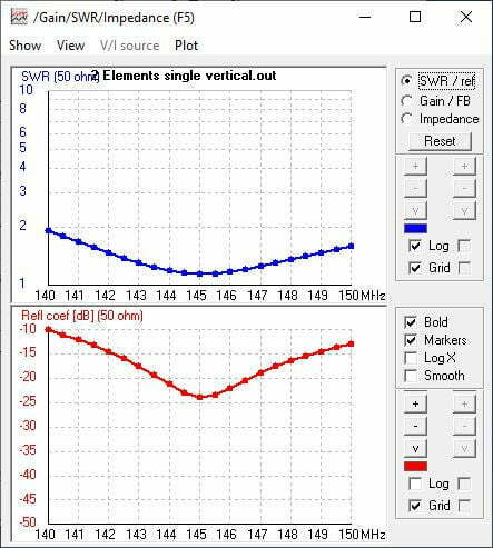
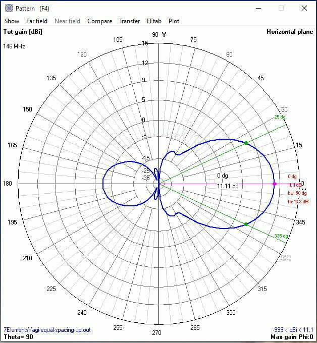
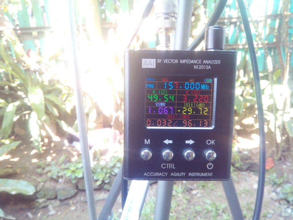
Antenna frequency response/tuning
Antenna frequency response from antenna analyzer is very much similar to the modelling results from 4Nec2.