Categories
Antenna Plans

2.42 Ghz 15 Element High Gain Yagi Antenna for WiFi

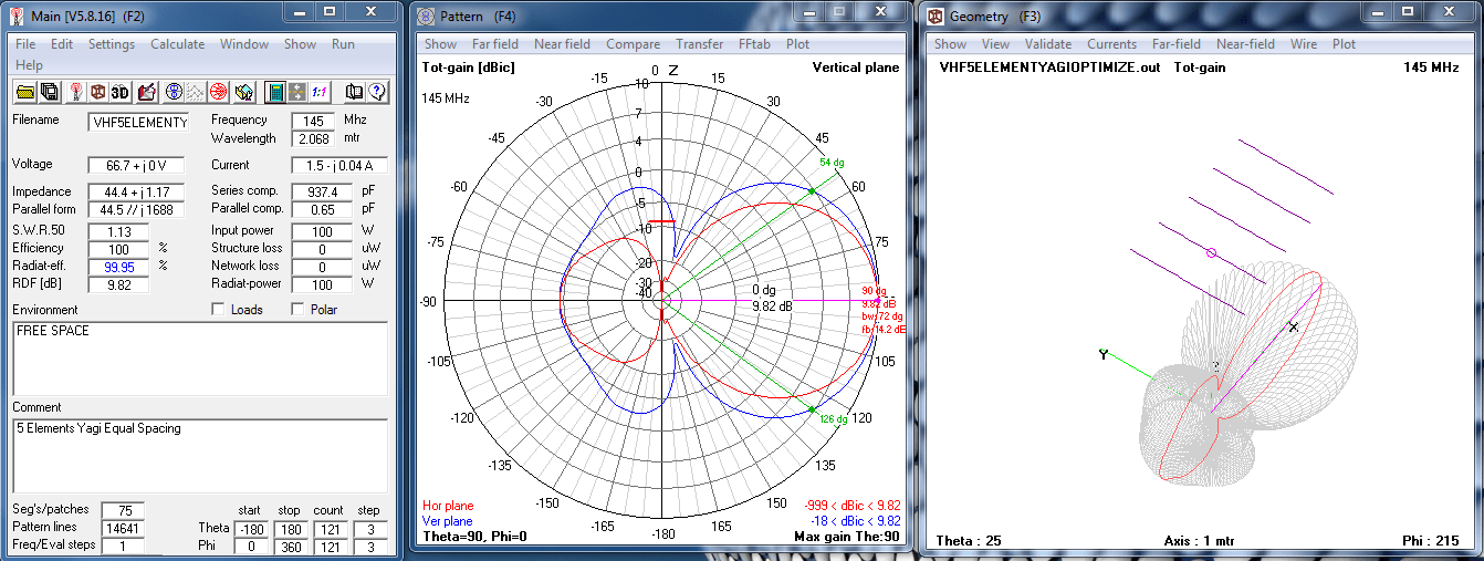
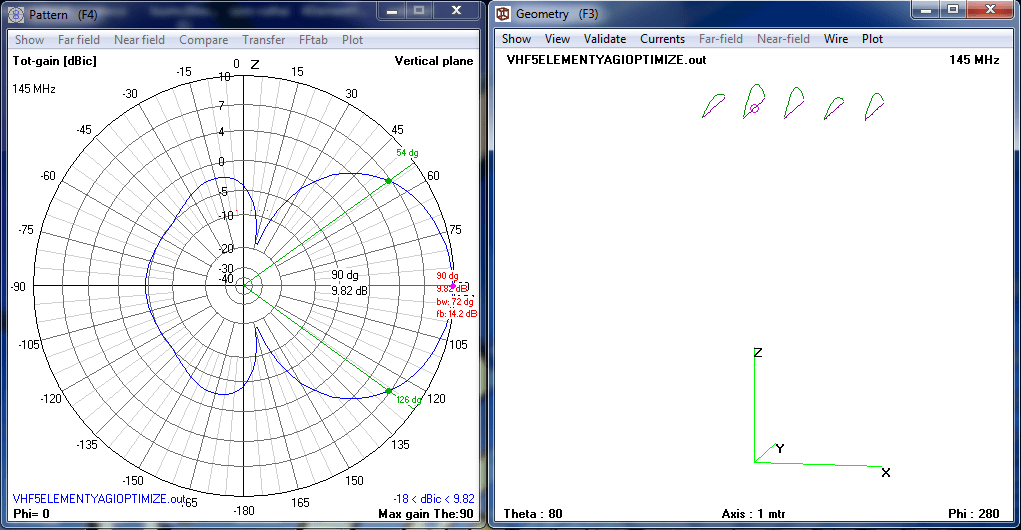
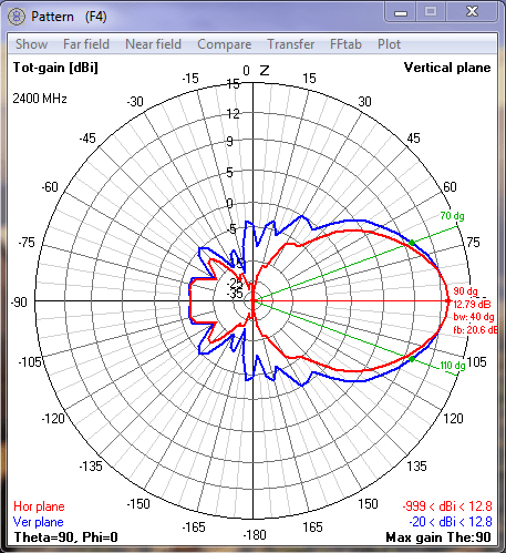
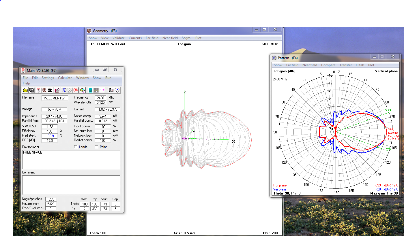
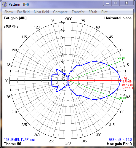
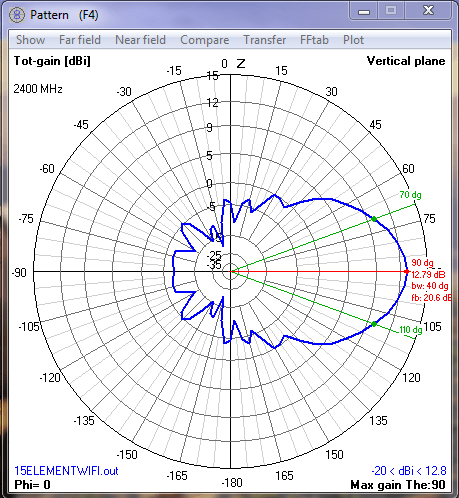
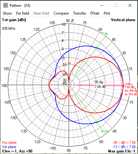
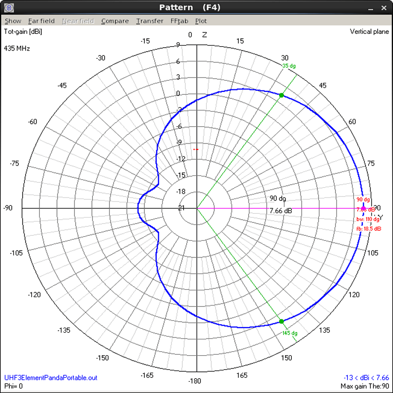
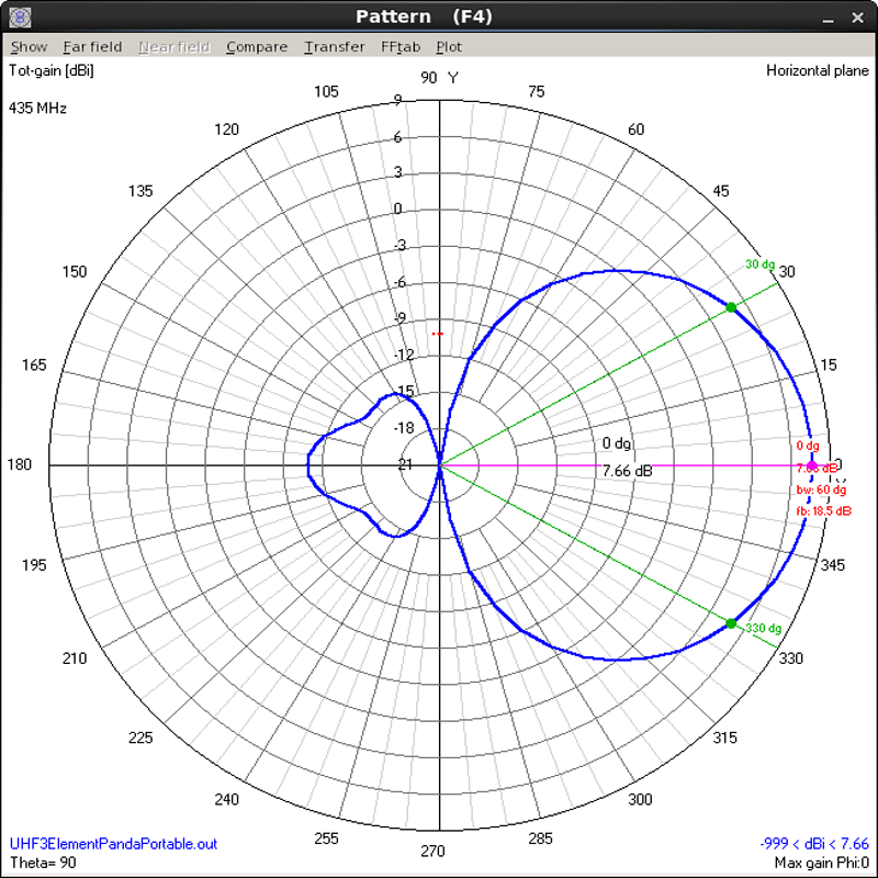
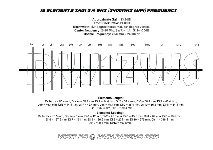
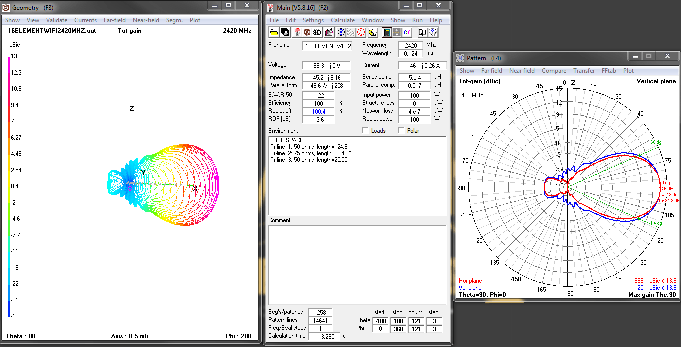
Improving on the design of my 15 Element Yagi Antenna for 2.4Ghz Wifi band, now with a much cleaner pattern no side lobes and higher front to back ratio at 24.8 dB. This antenna is pretty much usable from to 2340 Mhz to 2460 Mhz with less than 2:1 SWR this is centered at 2420Mhz with 1:1 SWR and about -30dB S11 antenna reflection coefficient.

2420Ghz WiFi Antenna


Download the PDF Document Here

WiFi 2.420Ghz Pattern

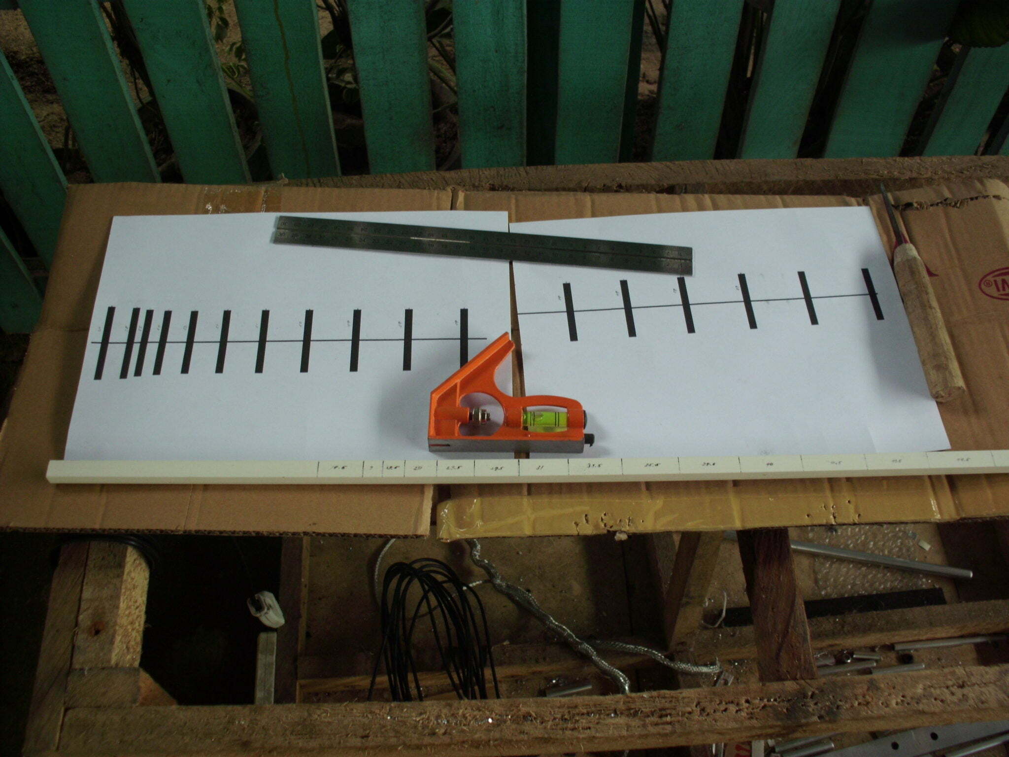
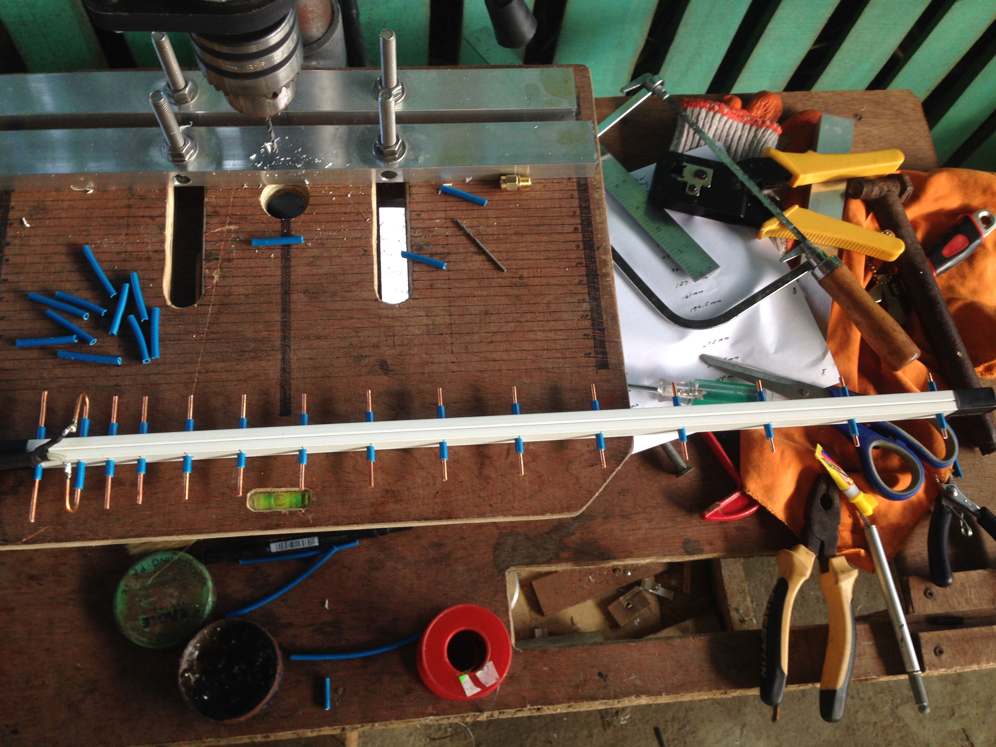
Im still using the same materials to build the antenna

Materials Lists
1. 12mm x 8mm uPvc moulding (Boom)
2. #12AWg solid wire for elements
3. Measuring tool / precision cutter
4. 1 SMA female connector
5. Coaxial cable suitable for SMA connector
6. Sandpaper or file tool for removing rough edges of the elements

antenna materials

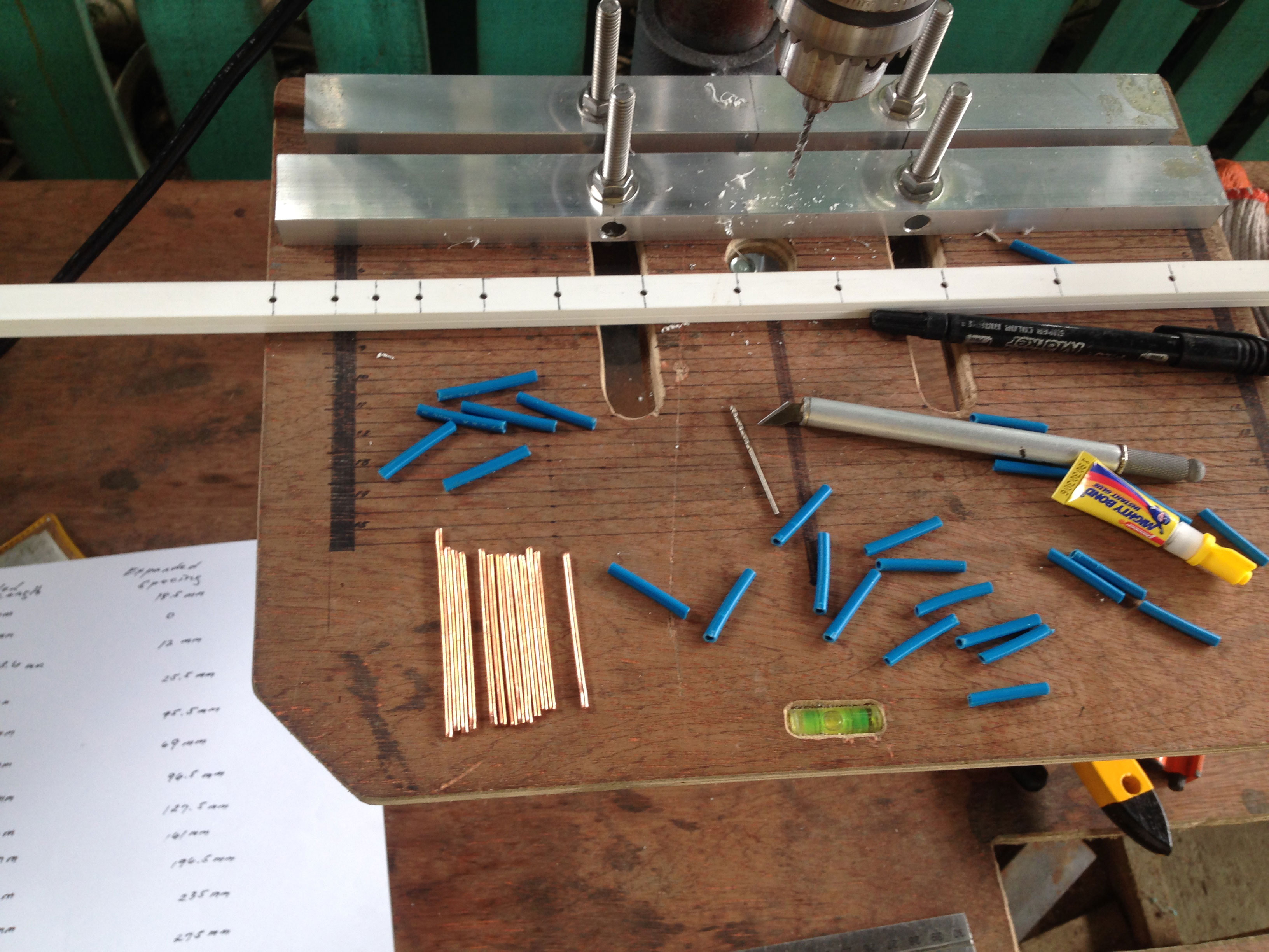
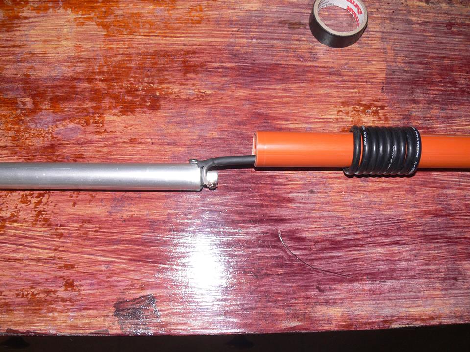
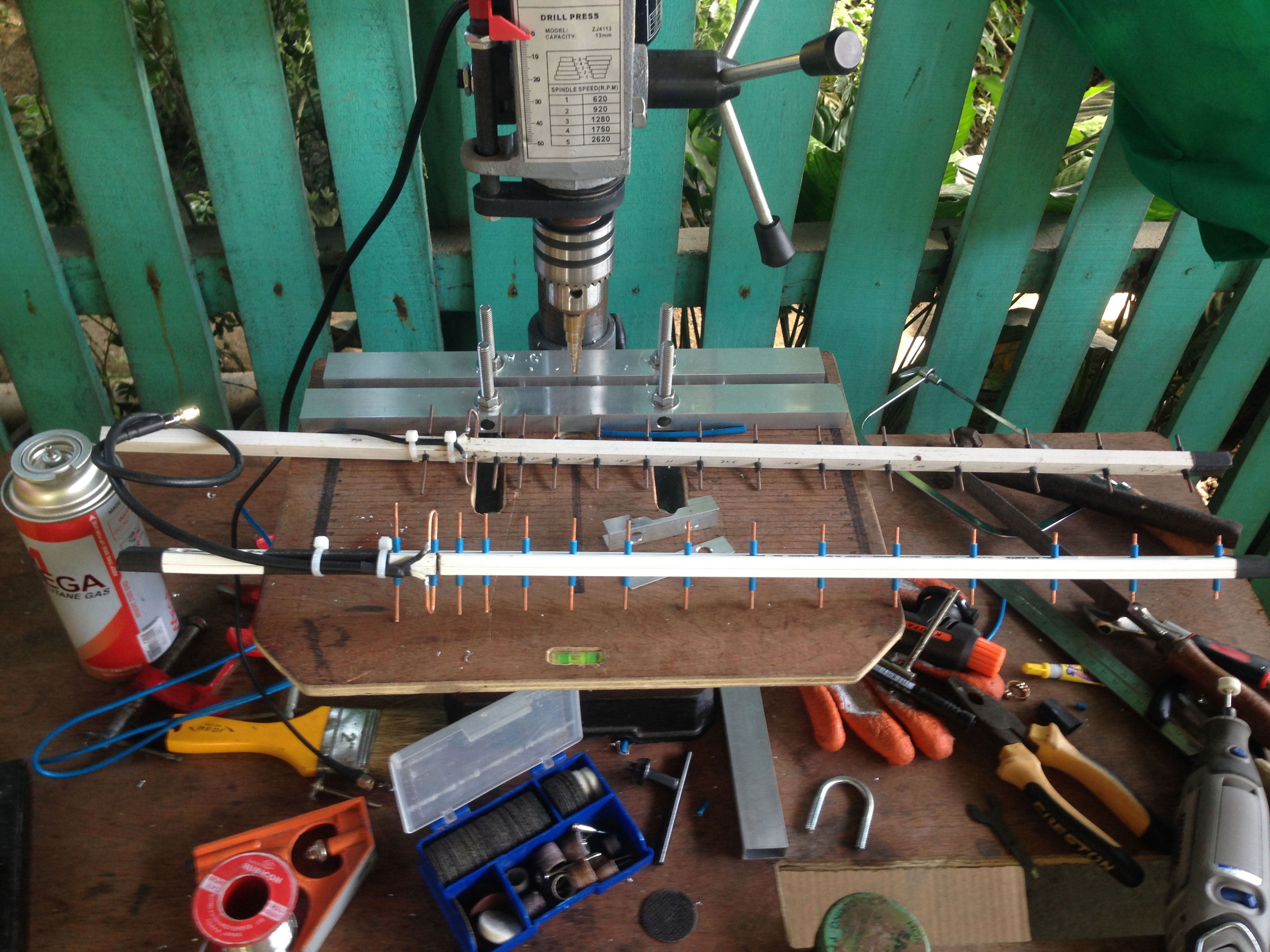
Building it is pretty straight forward just cut and paste (lol) bend the driven element and feed it with a 50 ohm coaxial cable rated for WiFi frequency, and check the SWR of the antenna.

Cut and paste the elements directly to the boom
Cut and paste the elements directly to the boom use the wire insulators as fittings to glue on the boom

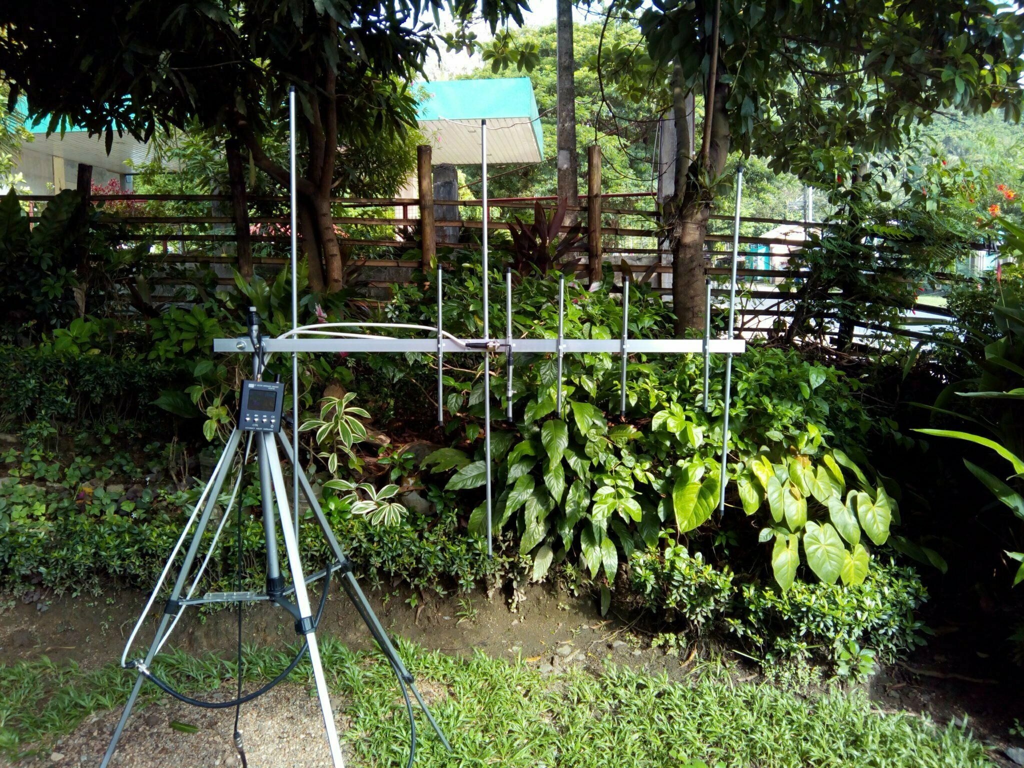
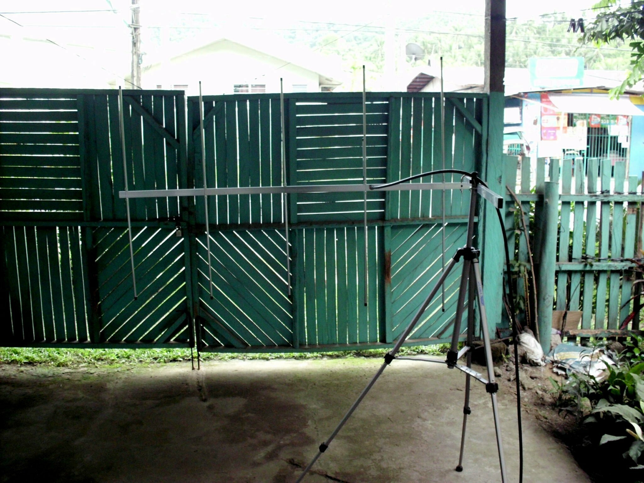
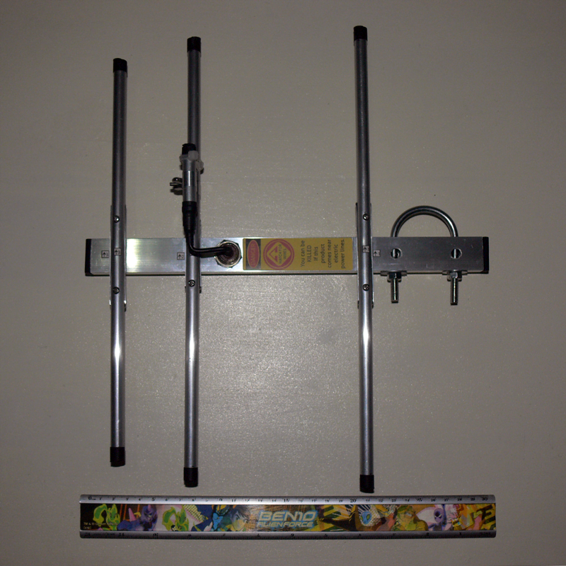
Here’s the finished antenna side by side with my previous build.

Finished antenna
Finished antenna with center frequency at 2.42Ghz

SWR testing video of 15 Element 2.4Ghz yagi antenna

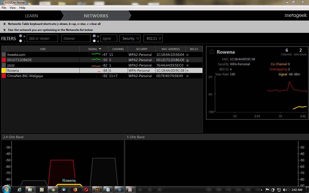
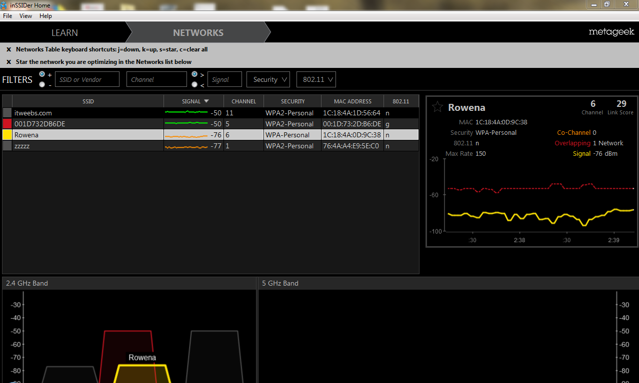
Actual receive analysis and link performance of the yagi antenna

Categories
Antenna Plans

Build the 3 x 5 Elements 2m/70cm Dualband Yagi

Build your own 2m/70cm 3 Elements VHF by 5 Elements UHF Yagi antenna with excellent gain for both VHF and UHF operation. This antenna is designed for amateur band frequency for both VHF (2m) and UHF (70cm). The antenna has good reflection coefficient and VSWR ratio @ 1.2:1 at center frequency and 1.7:1 at band edge.

Antenna Specs from 4Nec2

VHF Gain: 7.25dBi @ 145Mhz
Beamwidth: 114° degrees
Front to Back Ratio: 14.1dB
VSWR: 1.0:1

Expected pattern VHF

UHF Gain: 10dBi @ 440Mhz
Beamwidth: 60° degrees
Front to Back Ratio: 14.4dB
VSWR: 1.2:1

Expected pattern UHF

Building Video 3 Elements by 5 Elements 2m/70cm Dual band Yagi including Tuning

Material list for 3×5 Elements Dualband Yagi

1. 1″ X 0.5″ Rectangular Aluminum tubing for the boom
2. 3/8″ Aluminum tubing for antenna elements
3. 1cm Outside diameter antenna tubing for elements holder
4. 2pc SO239 connector
5. Pop rivets / Rivet tool
6. #12 AWG Copper wire with insulation (12″for Gamma match)
7. Soldering iron
8. 10pcs Stainless steel nuts and bolts 20mm length 3mm diameter
9. 1pc, Butterfly nut and 1 bolt 18mm length 3mm diameter
10. Aluminum plate 0.5mm thickness
11. 4 X 2″ Aluminum tube for bracket
12. Collapsible tube (shrinkable tubes)

Gamma Match for Dualband Yagi

Categories
Antenna Plans

3 Elements Yagi 2m at 146Mhz dimensions

Materials list

3 Elements Yagi Antenna Materials List

1″ X 0.5″ Rectangular Aluminum tubing for the boom
3/8″ Aluminum tubing for antenna elements
1cm Outside diameter antenna tubing for elements holder
1pc SO239 connector
Pop rivets / Rivet tool
#12 AWG Copper wire with insulation (12″for Gamma match)
Soldering iron
6pcs Stainless steel nuts and bolts 20mm length 3mm diameter
1, Butterfly nut and 1 bolt 18mm length 3mm diameter
Aluminum plate 0.5mm thickness
Collapsible tube (shrinkable tubes)

Antenna Patterns

To check the antenna pattern and expected gain if the antenna will perform similarly on other bands these are the results with both slight increased in SWR and little decreased in gain on 144Mhz and 148Mhz respectively but the expected pattern are generally the same. I’m using 4NEC2 for antenna simulation and analysis.

Predicted antenna pattern for 146Mhz
Predicted antenna pattern for 144Mhz
Predicted antenna pattern for 148Mhz
Predicted VSWR 140Mhz
Predicted VSWR 146Mhz
Predicted VSWR 154Mhz

See the performance testing video here on my youtube channel. As you can see in this video the yagi antenna is performing well on a mountainous terrain with lush vegetation.

Antenna Matching Technique

Antenna matching for this yagi is by Gamma Match which is similar to the one I used on my previous build for 3 Elements Yagi Gamma Match or 4 Elements Yagi Gamma Match. Use whatever you like.

Categories
Antenna Plans

Build a Sleeve Dipole Antenna for 2m VHF

Sleeve Dipole Antenna
Build a 2m VHF lightweight sleeve dipole antenna. A compact portable antenna and easy for deployment. You can even operate the dipole while holding it. Building it is easy just follow the antenna plans below. The antenna specifications are below including the testing video.

Antenna Gain: 3dBi
Pattern: Omni
Features: Lightweight and Portable easy deployment

Sleeve dipole

MATERIALS
3/8” round tube aluminum
1” round tube aluminum
2pc rubber or plastic stopper
2pc self tapping screw
RG58 Coax
SO239 or PL259 Connector
Hose Clamp

Sleeve Dipole

Wiring the Feedpoint

Wiring the feedpoint

Antenna Measurements

Performance Testing

Categories
Antenna Plans

Build the 5 Elements 2m VHF Yagi for the homebrewers

Antenna Matching: This is a gamma match antenna you can use the same gamma match I used for building the 4 Elements Gamma Match Yagi you may open the link here: https://dw1zws.com/building-the-gamma-match-for-4-elements-yagi/

To obtain the antenna pattern and approximate gain I used 4NEC2

Vertical Pattern
Horizontal Pattern
Current Magnitude
Current and Phase

For the SWR results and measurement of this 5 Element 2m VHF Yagi you may see it here on the link below:
https://dw1zws.com/5-elements-yagi-swr-response/

Categories
Antenna Plans

Build a 15 Element Yagi antenna for 2.4Ghz WiFi

Building a 15 Element Yagi for 2.4Ghz Wifi frequency. This antenna build is very useful for extending your wifi range indoor or outdoor. The approximate gain of this 15 element yagi is approximately 13dBi with a good front to back ratio of 20.6dB. Beamwith is 40° horizontal and 70° vertical.

Materials Lists
1. 12mm x 8mm uPvc moulding (Boom)
2. #12AWg solid wire for elements
3. Measuring tool / precision cutter
4. 1 SMA female connector
5. Coaxial cable suitable for SMA connector
6. Sandpaper or file tool for removing rough edges of the elements

Finished 15 Element 2.4Ghz Yagi
15 Element 2.4Ghz Yagi

Antenna Dimensions:

Download the PDF Document here

Antenna Gain/Patterns:
Gain and and antenna patterns are from 4NEC2 antenna modelling software.

Combined

Horizontal:

Vertical:

Laying out:

Layout and measurements

Folded Dipole:

Folded Dipole Driven Element
Ready for testing

Some direct measurements from neighbors WiFi access point:

Screen shot dBm measurement taken from a dipole

This first screen shot reading is from a WiFi card with a 5dBi dipole antenna

Screen shot dBm measurement taken from 15 Element Yagi

The second screen shot is taken from 15 Element Yagi antenna build taken indoors

As we can see from the above screen shots the initial measurement from a dipole yields -88dBm our reading from the yagi -76dBm direct calculation from the 2 values ( -88dBm – -76dBm = -12dBm) our yagi gain is almost equal to the theoretical gain of 13dBi. The above measurements are taken indoors the WiFi card is connected to a laptop.

Categories
Antenna Plans

How to make a Gamma Match?

So you follow the tutorial article on how to make the 3 Element Yagi on this page. You’ve even watched the tutorial video on how I build the 3 element yagi and wanted to duplicate it. You’re all set with all the materials at hand and most importantly you’ve got the perfect time to do it now. So you proceeded with the project, you cut the elements, marked the spacing, mounted the elements holder and things are looking good. Except for the last part the diagram seems too complicated to follow. So worry not this is the tutorial video on how I build the gamma match for my antenna build.

So to recap:

The gamma accomplishes 3 things:

1. Usually it’s a small diameter wire parallel and in close vicinity with the main radiating element, it will carry only a fraction of the main element current while being exposed to the same electrical field strength. This turns it in an effective up-transformer of the antenna input impedance. A sort of folded dipole performing an impedance step up.

2. It forms together with the main radiating element a closed wire stub, adding inductance to the antenna input impedance. If it is not required for matching, this additional inductance can be cancelled out with a lumped capacitor in series. A parallel shorted transmission line stub, adding shunt inductance.

3. The sheath of the coaxial feed-line (braid) is connected to the center of the main radiating element. When properly connected, a gamma-match also serves as a balanced to unbalanced converter or balun.

Here’s the how to video:

If you want a more in depth discussion and mathematics behind the gamma match read and download the gamma match document below.

Download the document here

Categories
Antenna Plans

Original patent design for Folded Dipole antenna

A folded dipole is an antenna with the ends folded back forming a loop. The impedance of this antenna is around 300 Ω, so you may want to use a transformer or a λ/4 long piece of 120 Ω coaxial or 75 Ω cable to match this impedance to 50 Ω. Geometry is not that critical.

Download the PDF Document here

Categories
Antenna Plans

Yagi Antenna Design (U.S Department of Commerce / National Bureau of Standards

The Yagi-Uda antenna, commonly known as the Yagi, was invented in 1926 by by Dr. H. Yagi and Shintaro Uda. Its configuration normally consists of a number of directors and reflectors that enhance radiation in one direction when properly arranged on supporting structure.

The results of the measurements carried out in this study are presented in graphical form. They are intended to provide a simple means of designing a Yagi antenna of practical dimensions with maximum gain for the configuration under consideration. The purpose of these tests was to determine the following:

a. Effect of reflector spacing on the gain of a dipole antenna
b. Effect of different equal length directors, their spacing and number on realizable gain.
c. Effect of different diameters and lengths of directors on realizable gain.
d. Effect of the size of a supporting boom on the optimum length of parasitic elements.
e. Effect of spacing and stacking of antennas on gain.
f. Measured radiation patterns of different Yagi configurations

Download the PDF Document here

Categories
Antenna Plans

3 Elements Yagi 70cm (Lightweight End Mount) Compact

Building a high performance 3 Elements lightweight end mount Yagi antenna for 70cm UHF band centered at 435 Mhz. This Yagi build exhibits a gain of 7.66dBi at the center frequency 435Mhz for use in the Philippine UHF amateur band. Front to back ratio is 18.5dB, Vertical Beamwidth 106°, Horizontal Beamwidth 64°. Just like my previous design it uses direct coupling of feed point to boom and a gamma match to tune the antenna. This antenna will cover 430-445 Mhz UHF Amateur Band.

3 Element UHF Compact

Download yagi dimensions here

3 Elements Yagi 70cm UHF Antenna Materials List

1. 1″ X 0.5″ Rectangular Aluminum tubing for the boom
2. 3/8″ Aluminum tubing for antenna elements
3. 1cm Outside diameter antenna tubing for elements holder
4. 1pc SO239 connector
5. Pop rivets / Rivet tool
6. #12 AWG Copper wire with insulation (12″for Gamma match)
7. Soldering iron
8. 6pcs Stainless steel nuts and bolts 20mm length 3mm diameter
9. 1, Butterfly nut and 1 bolt 18mm length 3mm diameter
10. Aluminum plate 0.5mm thickness
11. Collapsible tube (shrinkable tubes)

Measurements

1. Boom Length 32 cm (Use rectangular aluminum tubing)
2. Reflector Element (length) = 34.00cm
3. Driven Element (length) = 32.50cm
4. Director Element length) = 29.50cm

Spacing:

Boom end to 1st U Bolt (hole) = 1.5cm
1st U Bolt to 2nd U Bolt (mounting holes) = 4.5cm
2nd U Bolt hole to Reflector = 3.81cm
Reflector to Driven = 12.60cm
Driven to Director = 5.40cm
Director to End of boom = 2.50cm

To increase the performance you may also configure the antenna in stack configuration by making two antenna’s and connect it with a phasing harness for increased performance.

Antenna Gain Simulation and Signal Pattern Using 4Nec2 antenna modeling.

Combined Pattern

Combined UHF 435Mhz

Gain 7.66dBi
Front to back ratio is 18.5dB
Vertical Beamwidth 106°
Horizontal Beamwidth 64°

Vertical Pattern


Horizontal Pattern

Real Ground