Building the gamma match for 3 Elements Yagi UHF 70cm 435Mhz
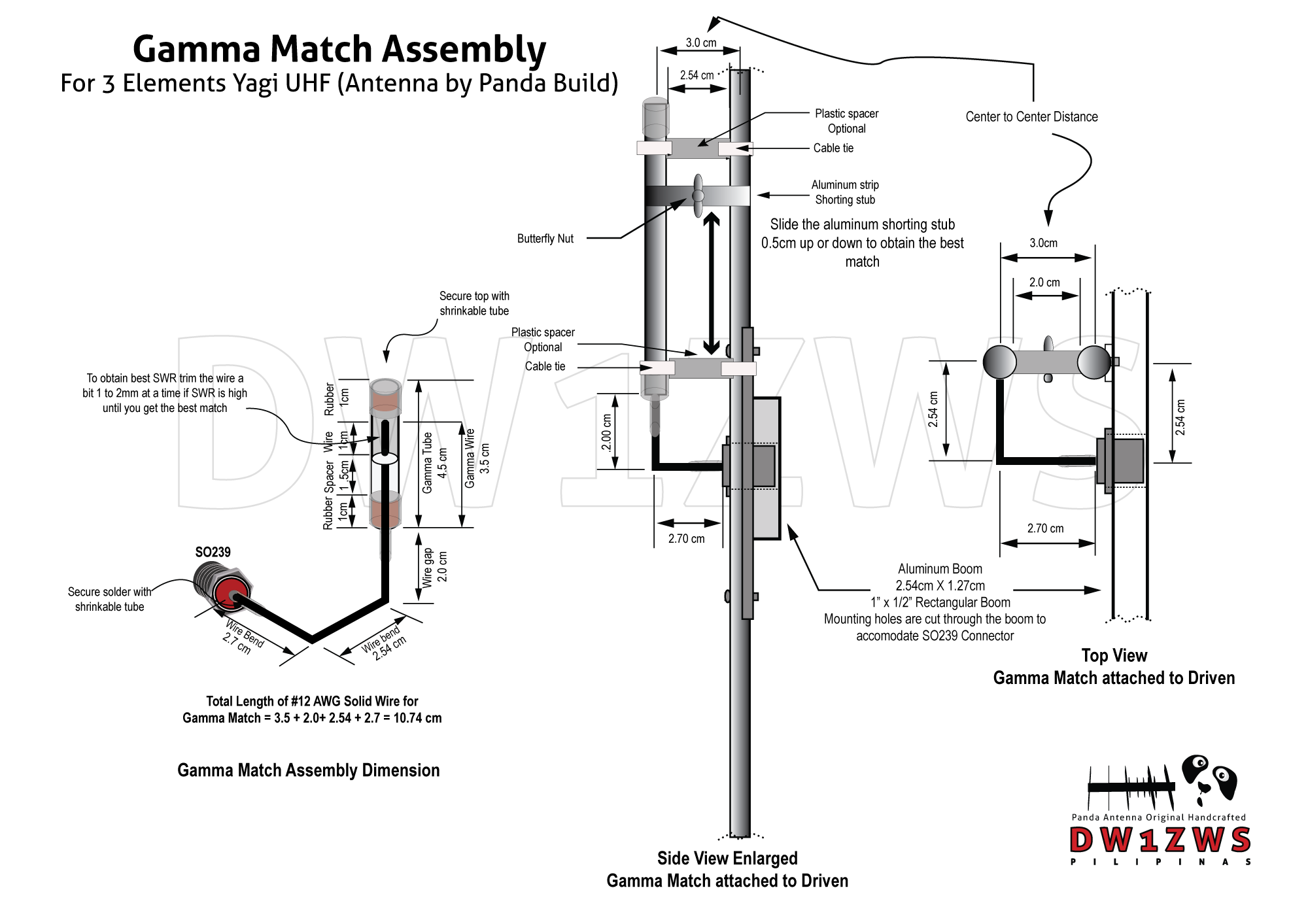
Just like the gamma match for our 5 Elements Yagi the construction technique for building the gamma match for the 3 Elements UHF Yagi are similar (tolerance level of 3% to 5% on measurements for building the gamma match is fine). The gamma tube for the 5 Elements UHF Yagi is exactly 4.5 cm. Please refer to the diagram for actual measurements. This yagi will give you a good coverage from 430Mhz to 445Mhz on single configuration @ 1:1 SWR on center frequency 435Mhz and about 2:1 SWR on band edges.
Building the gamma match for 5 Elements Yagi UHF Just like the gamma match for our 4 Elements Yagi the construction technique for building the gamma match for the 5 Elements UHF Yagi are similar, except for major changes on measurements. The gamma tube for the 5 Elements UHF Yagi is exactly 4.5 cm. Please refer to the diagram for actual measurements. This yagi will give you a good coverage from 430Mhz to 450Mhz on single configuration @ 1:1 SWR on center frequency 435Mhz and about 2:1 SWR on band edges.
So what is a gamma match in the context of the driven element and why should we use it?.
A gamma match is an adjustable device used for feeding and matching an antenna, coupled to the driven element of a beam to match the 50 ohm coaxial feed-line.
The gamma accomplishes 3 things:
1. Usually it’s a small diameter wire parallel and in close vicinity with the main radiating element, it will carry only a fraction of the main element current while being exposed to the same electrical field strength. This turns it in an effective up-transformer of the antenna input impedance. A sort of folded dipole performing an impedance step up.
2. It forms together with the main radiating element a closed wire stub, adding inductance to the antenna input impedance. If it is not required for matching, this additional inductance can be cancelled out with a lumped capacitor in series. A parallel shorted transmission line stub, adding shunt inductance.
3. The sheath of the coaxial feed-line (braid) is connected to the center of the main radiating element. When properly connected, a gamma-match also serves as a balanced to unbalanced converter or balun.
A note of caution: This gamma match would work only on the specified antenna design. Since this is a matching assembly you need to adjust it to your specific design if you happen to re-purpose it for other antenna project. Probably it’s one of the reason why most of the available design on the internet provides only the elements measurements (antenna matching is a subject for experimentation).
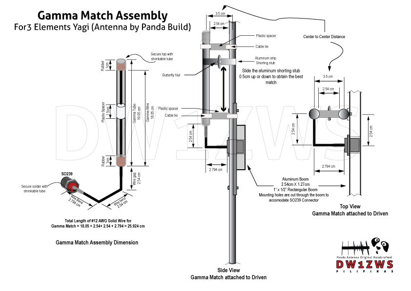
1. A piece of #12AWG solid wire (refer to diagram for actual measurements at least 12″ cut accordingly) 2. A piece of 3/8 aluminum tubing for gamma tube (see diagram for actual measurement) 3. 1pc SO239 Connector and 1.5cm round plastic insulator (the center insulator of RG8 coaxial cable is suitable) 4. 1pc Butterfly nut and 1pc bolt 18mm length 3mm diameter 5. Aluminum plate 0.5mm thickness (cut to strip length of 1 25.4cm x 1cm adjust accordingly for shorting stub) 6. Rubber stopper 1cm thickness for both ends of gamma tube 7. Soldering iron and soldering lead to solder the piece of wire to SO239 8. Collapsible tube (shrinkable tubes) for securing the ends of gamma match assembly. 9. Plastic spacer (a 1.2cm rectangular plastic wire conduit is suitable uPVC moldings) (Optional) 10. 2pcs of aluminum plates measuring 2.54cm in length and 1cm thickness (use a piece of boom to make one, use it to sandwich the aluminum strip and secure it with the butterfly nut) 11. Cable tie to secure plastic spacer. (Optional)
To build the gamma match, cut the required materials as seen on the diagram. Insert the round plastic spacer to the middle of solid wire and put a rubber stopper at both ends of the gamma tube. You need to cut a hole in the middle of the bottom rubber stopper to facilitate inserting the wire to the gamma tube. Bend the wire to the actual measurement in the diagram and solder the SO239 connector to the wire. Secure the gamma match assembly using the shrinkable tube to make it water tight. Put the plastic spacer in between the driven element and the gamma match and secure it with the cable tie (Optional for this build). Finally attach the gamma match to driven element and and sandwich the shorting stub with 2pcs aluminum plates and secure it with the butterfly nut. Use the shorting stub to tune your antenna.
To build the 5 Elements UHF Yagi you may follow the direction for building the 3 Elements Yagi. The elements for UHF antenna are shorter and it needs more precise cutting. Follow the measurements on the diagram including spacing between the elements and when built successfully it will give you a very desirable 11 dBi gain or about or about 8.85dBd.
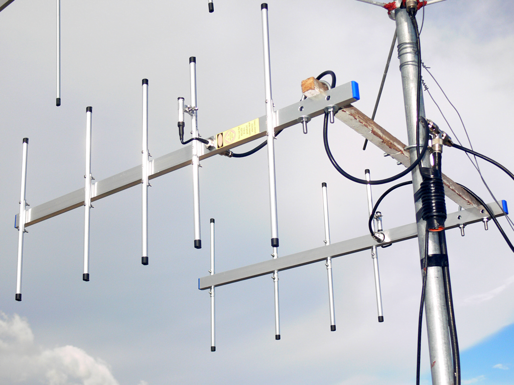
To increase the performance you may also configure the antenna in stack configuration by making two antenna’s and connect it with a phasing harness for increased performance.
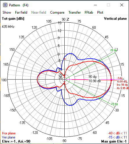
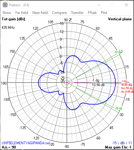
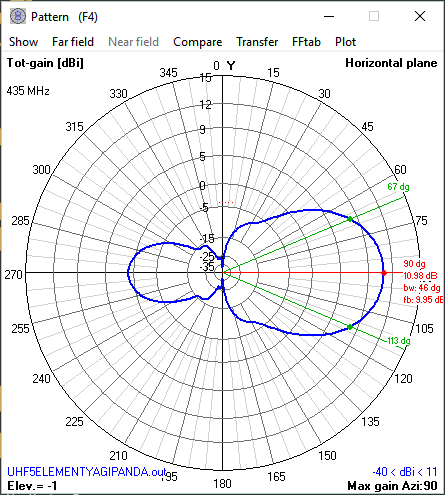
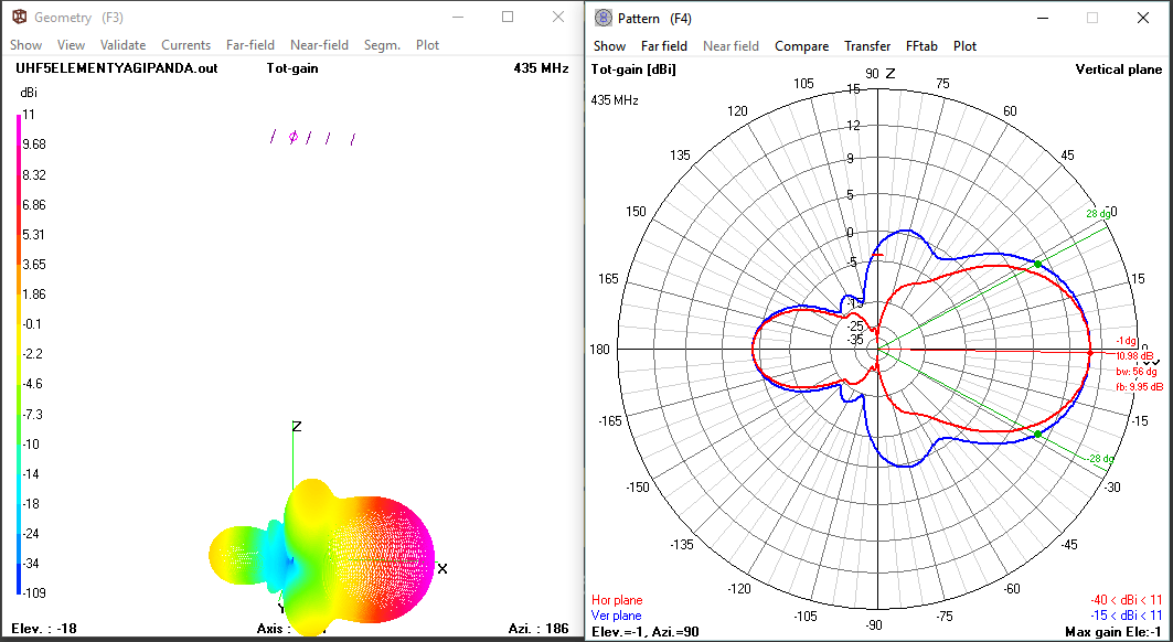
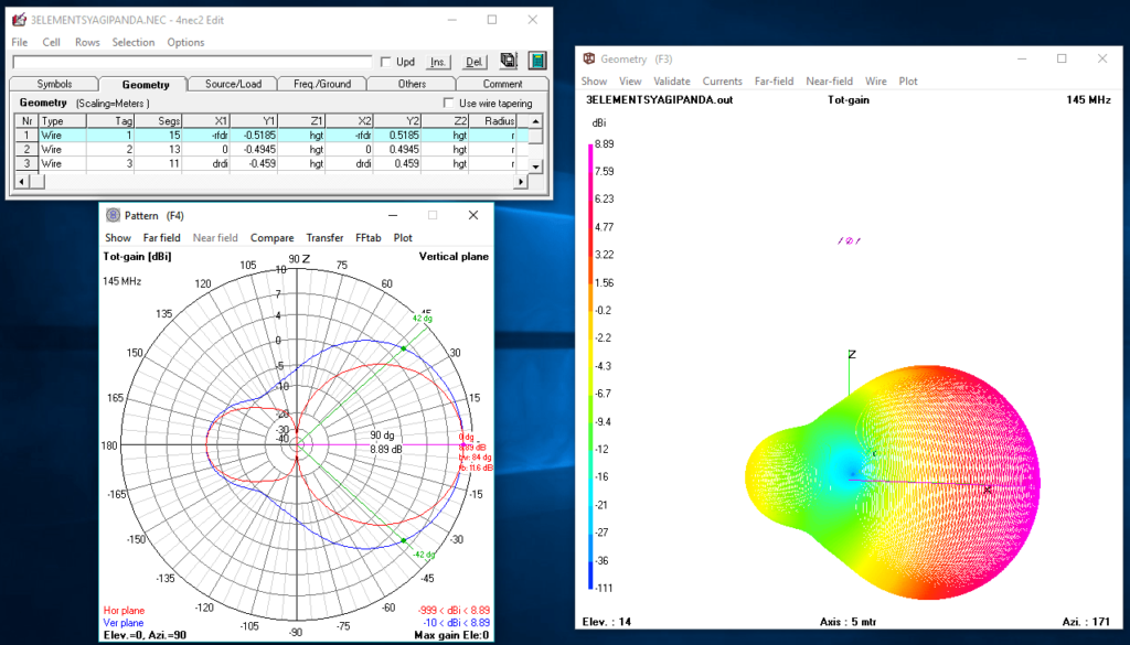
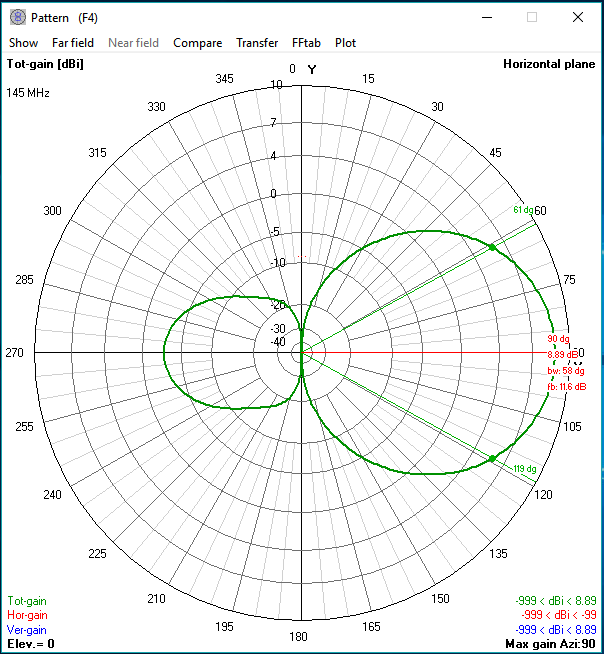
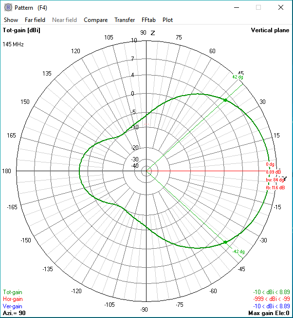
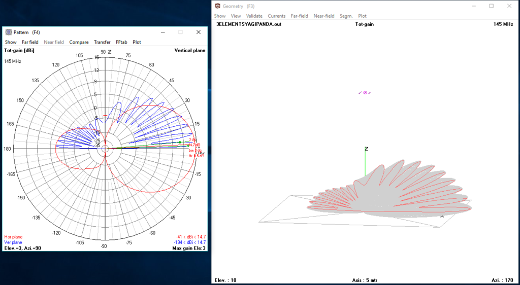
Antenna Gain Simulation and Signal Pattern Using 4Nec2 antenna modeling for individual antenna.
Front to Back Ratio: 9.92dB Antenna Gain: 10.98 ~ 11dBi Beamwitdh: 56° Vertical 46° Horizontal
Just like the gamma match for our 3 Elements Yagi the construction technique for building the gamma match for the 4 Elements Yagi are similar, except for some measurement changes. The gamma tube for the 4 Elements yagi is about 2.54 cm shorter. Please refere to the diagram for actual measurements. This yagi will give you a good coverage from 142Mhz to 148Mhz on single configuration @ 1:1 SWR on center frequency 145Mhz and about 2:1 SWR on band edges.
So what is a gamma match in the context of the driven element and why should we use it?.
A gamma match is an adjustable device used for feeding and matching an antenna, coupled to the driven element of a beam to match the 50 ohm coaxial feed-line.
The gamma accomplishes 3 things:
1. Usually it’s a small diameter wire parallel and in close vicinity with the main radiating element, it will carry only a fraction of the main element current while being exposed to the same electrical field strength. This turns it in an effective up-transformer of the antenna input impedance. A sort of folded dipole performing an impedance step up.
2. It forms together with the main radiating element a closed wire stub, adding inductance to the antenna input impedance. If it is not required for matching, this additional inductance can be cancelled out with a lumped capacitor in series. A parallel shorted transmission line stub, adding shunt inductance.
3. The sheath of the coaxial feed-line (braid) is connected to the center of the main radiating element. When properly connected, a gamma-match also serves as a balanced to unbalanced converter or balun.
A note of caution: This gamma match would work only on the specified antenna design. Since this is a matching assembly you need to adjust it to your specific design if you happen to re-purpose it for other antenna project. Probably it’s one of the reason why most of the available design on the internet provides only the elements measurements (antenna matching is a subject for experimentation).
1. A piece of #12AWG solid wire (refer to diagram for actual measurements at least 12″ cut accordingly) 2. A piece of 3/8 aluminum tubing for gamma tube (see diagram for actual measurement) 3. 1pc SO239 Connector and 1.5cm round plastic insulator (the center insulator of RG8 coaxial cable is suitable) 4. 1pc Butterfly nut and 1pc bolt 18mm length 3mm diameter 5. Aluminum plate 0.5mm thickness (cut to strip length of 1 25.4cm x 1cm adjust accordingly for shorting stub) 6. Rubber stopper 1cm thickness for both ends of gamma tube 7. Soldering iron and soldering lead to solder the piece of wire to SO239 8. Collapsible tube (shrinkable tubes) for securing the ends of gamma match assembly. 9. Plastic spacer (a 1.2cm rectangular plastic wire conduit is suitable uPVC moldings) 10. 2pcs of aluminum plates measuring 2.54cm in length and 1cm thickness (use a piece of boom to make one, use it to sandwich the aluminum strip and secure it with the butterfly nut) 11. Cable tie to secure plastic spacer.
To build the gamma match, cut the required materials as seen on the diagram. Insert the round plastic spacer to the middle of solid wire and put a rubber stopper at both ends of the gamma tube. You need to cut a hole in the middle of the bottom rubber stopper to facilitate inserting the wire to the gamma tube. Bend the wire to the actual measurement in the diagram and solder the SO239 connector to the wire. Secure the gamma match assembly using the shrinkable tube to make it water tight. Put the plastic spacer in between the driven element and the gamma match and secure it with the cable tie. Finally attach the gamma match to driven element and and sandwich the shorting stub with 2pcs aluminum plates and secure it with the butterfly nut. Use the shorting stub to tune your antenna.
So you’ve decided to build the 3 Elements Yagi, you’ve checked all the diagrams and tutorial video on building the Yagi. You decided that everything is easy, except on how would you proceed in building the gamma match. Sure the tutorial video is enticing however it seems not clear on how things would fit in the context of the gamma match assembly.
So what is a gamma match in the context of the driven element and why should we use it?.
A gamma match is an adjustable device used for feeding and matching an antenna, coupled to the driven element of a beam to match the 50 ohm coaxial feed-line.
The gamma accomplishes 3 things:
1. Usually it’s a small diameter wire parallel and in close vicinity with the main radiating element, it will carry only a fraction of the main element current while being exposed to the same electrical field strength. This turns it in an effective up-transformer of the antenna input impedance. A sort of folded dipole performing an impedance step up.
2. It forms together with the main radiating element a closed wire stub, adding inductance to the antenna input impedance. If it is not required for matching, this additional inductance can be cancelled out with a lumped capacitor in series. A parallel shorted transmission line stub, adding shunt inductance.
3. The sheath of the coaxial feed-line (braid) is connected to the center of the main radiating element. When properly connected, a gamma-match also serves as a balanced to unbalanced converter or balun.
A note of caution: This gamma match would work only on the specified antenna design. Since this is a matching assembly you need to adjust it to your specific design if you happen to re-purpose it for other antenna project. Probably it’s one of the reason why most of the available design on the internet provides only the elements measurements (antenna matching is a subject for experimentation).
1. A piece of #12AWG solid wire (refer to diagram for actual measurements at least 12″ cut accordingly) 2. A piece of 3/8 aluminum tubing for gamma tube (see diagram for actual measurement) 3. 1pc SO239 Connector and 1.5cm round plastic insulator (the center insulator of RG8 coaxial cable is suitable) 4. 1pc Butterfly nut and 1pc bolt 18mm length 3mm diameter 5. Aluminum plate 0.5mm thickness (cut to strip length of 1 25.4cm x 1cm adjust accordingly for shorting stub) 6. Rubber stopper 1cm thickness for both ends of gamma tube 7. Soldering iron and soldering lead to solder the piece of wire to SO239 8. Collapsible tube (shrinkable tubes) for securing the ends of gamma match assembly. 9. Plastic spacer (a 1.2cm rectangular plastic wire conduit is suitable uPVC moldings) 10. 2pcs of aluminum plates measuring 2.54cm in length and 1cm thickness (use a piece of boom to make one, use it to sandwich the aluminum strip and secure it with the butterfly nut) 11. Cable tie to secure plastic spacer.
To build the gamma match, cut the required materials as seen on the diagram. Insert the round plastic spacer to the middle of solid wire and put a rubber stopper at both ends of the gamma tube. You need to cut a hole in the middle of the bottom rubber stopper to facilitate inserting the wire to the gamma tube. Bend the wire to the actual measurement in the diagram and solder the SO239 connector to the wire. Secure the gamma match assembly using the shrinkable tube to make it water tight. Put the plastic spacer in between the driven element and the gamma match and secure it with the cable tie. Finally attach the gamma match to driven element and and sandwich the shorting stub with 2pcs aluminum plates and secure it with the butterfly nut. Use the shorting stub to tune your antenna.
To build the 4 Elements Yagi you may follow the direction for building the 3 Elements Yagi except that you will add an additional parasitic element (director) which is about 5% shorter than the last element of the 3 elements yagi. The spacing are the same between the elements and when built successfully it will give you a very desirable 9.39dBi gain or about or about 7.24dBd.
To increase the performance you may also configure the antenna in stack configuration by making two antenna’s and connect it with a phasing harness for increased performance.
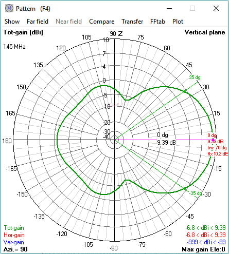
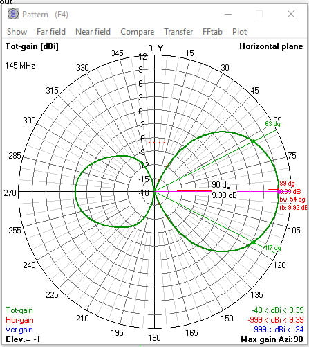
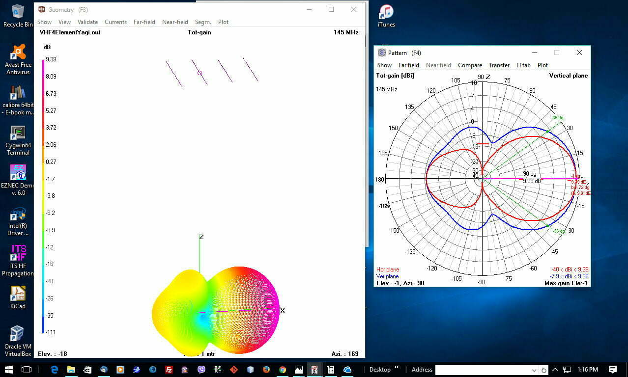
Antenna Gain Simulation and Signal Pattern Using 4Nec2 antenna modeling.
Front to Back Ratio: 9.92dB Antenna Gain: 9.39dBi Beamwitdh: 70° Vertical 54° Horizontal
Vertical Pattern 4 Elements YagiHorizontal Pattern 4 Elements YagiCombined pattern 4 Elements Yagi
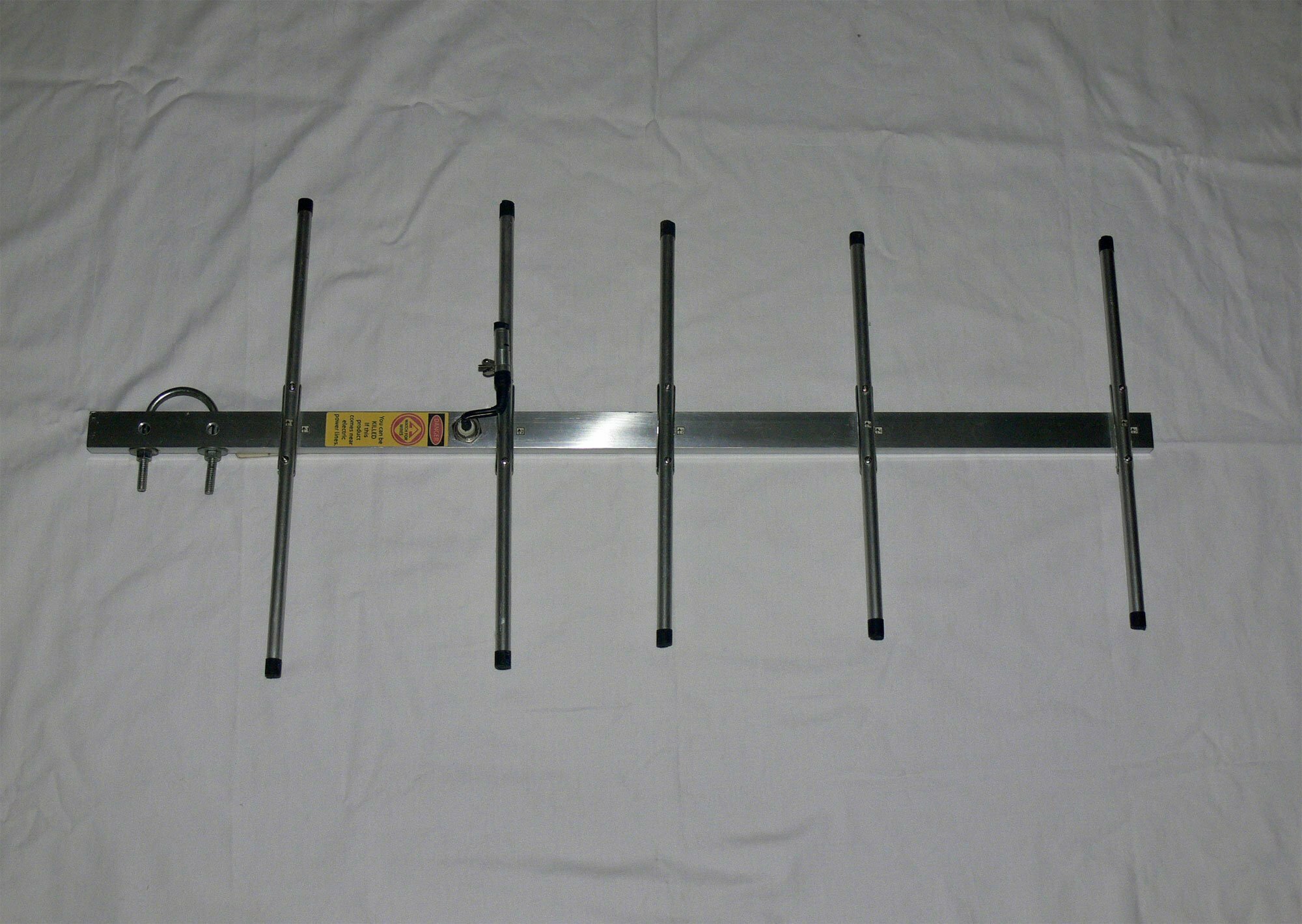
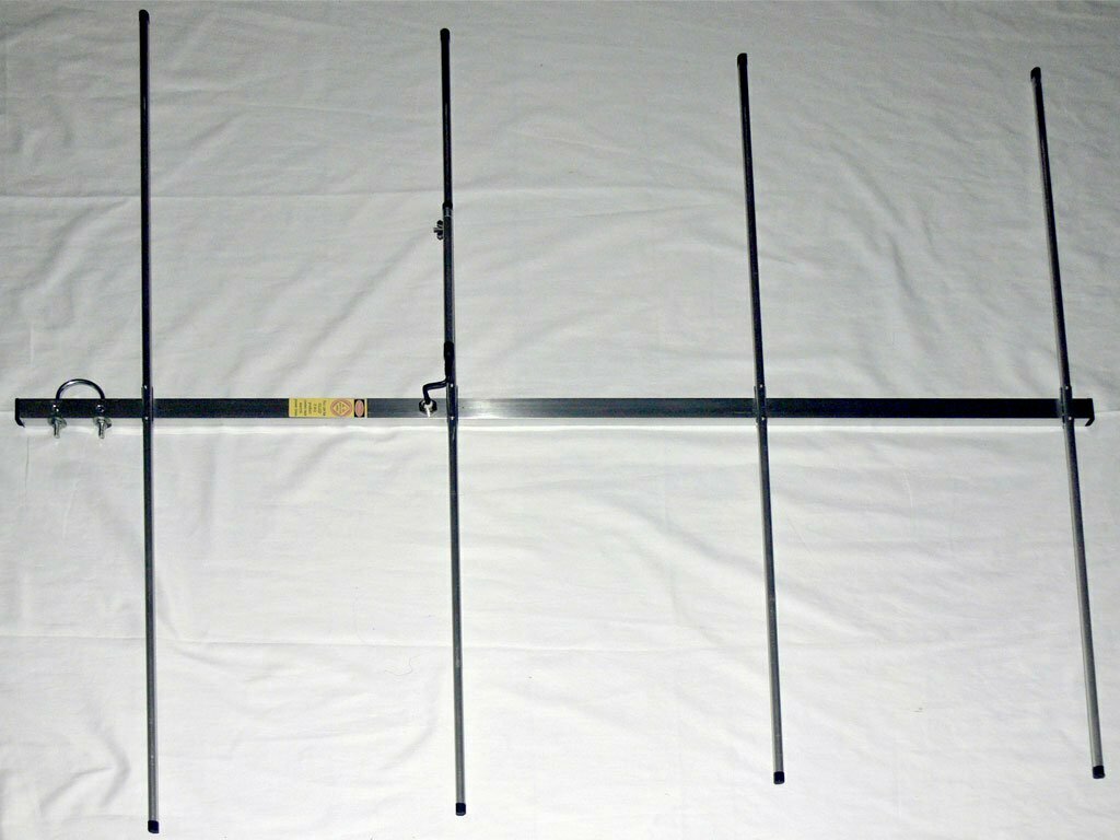
Building a high performance 3 Elements lightweight end mount Yagi antenna. The awesome Yagi antenna provides many advantages in a number of applications.This antenna has high gain allowing lower strength signals to be received. Yagi antenna has better directivity which enables interference levels to be minimized and have straight forward construction i.e; the Yagi antenna allows all constructional elements to be made from rods simplifying construction. The construction enables the antenna to be mounted easily on vertical and other poles with standard mechanical fixings.
3 Elements Yagi Antenna Materials List
1″ X 0.5″ Rectangular Aluminum tubing for the boom 3/8″ Aluminum tubing for antenna elements 1cm Outside diameter antenna tubing for elements holder 1pc SO239 connector Pop rivets / Rivet tool #12 AWG Copper wire with insulation (12″for Gamma match) Soldering iron 6pcs Stainless steel nuts and bolts 20mm length 3mm diameter 1, Butterfly nut and 1 bolt 18mm length 3mm diameter Aluminum plate 0.5mm thickness Collapsible tube (shrinkable tubes)
3 Element Yagi making, tuning and testing video
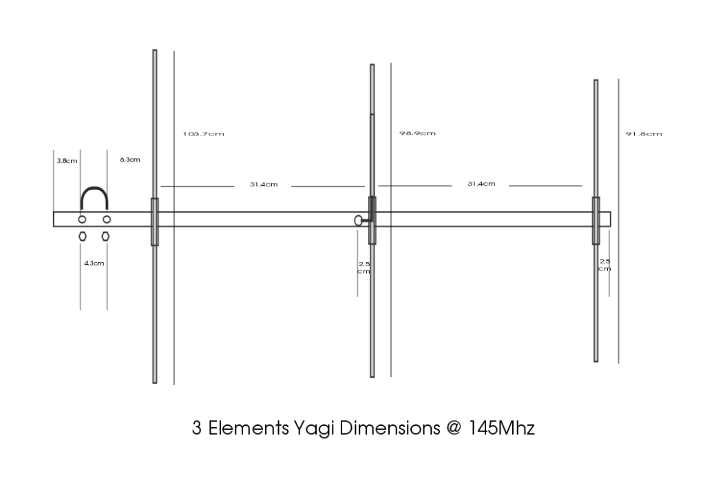
Measurements
1 Boom Length 80 cm (Use rectangular aluminum tubing) Reflector Element (length) = 103.7cm Driven Element (length) = 98.9cm Director Element length) = 91.8cm
We use cookies on our website to give you the most relevant experience by remembering your preferences and repeat visits. By clicking “Accept”, you consent to the use of ALL the cookies.
This website uses cookies to improve your experience while you navigate through the website. Out of these, the cookies that are categorized as necessary are stored on your browser as they are essential for the working of basic functionalities of the website. We also use third-party cookies that help us analyze and understand how you use this website. These cookies will be stored in your browser only with your consent. You also have the option to opt-out of these cookies. But opting out of some of these cookies may affect your browsing experience.
Necessary cookies are absolutely essential for the website to function properly. These cookies ensure basic functionalities and security features of the website, anonymously.
Cookie
Duration
Description
cookielawinfo-checkbox-analytics
11 months
This cookie is set by GDPR Cookie Consent plugin. The cookie is used to store the user consent for the cookies in the category "Analytics".
cookielawinfo-checkbox-functional
11 months
The cookie is set by GDPR cookie consent to record the user consent for the cookies in the category "Functional".
cookielawinfo-checkbox-necessary
11 months
This cookie is set by GDPR Cookie Consent plugin. The cookies is used to store the user consent for the cookies in the category "Necessary".
cookielawinfo-checkbox-others
11 months
This cookie is set by GDPR Cookie Consent plugin. The cookie is used to store the user consent for the cookies in the category "Other.
cookielawinfo-checkbox-performance
11 months
This cookie is set by GDPR Cookie Consent plugin. The cookie is used to store the user consent for the cookies in the category "Performance".
viewed_cookie_policy
11 months
The cookie is set by the GDPR Cookie Consent plugin and is used to store whether or not user has consented to the use of cookies. It does not store any personal data.
Functional cookies help to perform certain functionalities like sharing the content of the website on social media platforms, collect feedbacks, and other third-party features.
Performance cookies are used to understand and analyze the key performance indexes of the website which helps in delivering a better user experience for the visitors.
Analytical cookies are used to understand how visitors interact with the website. These cookies help provide information on metrics the number of visitors, bounce rate, traffic source, etc.
Advertisement cookies are used to provide visitors with relevant ads and marketing campaigns. These cookies track visitors across websites and collect information to provide customized ads.