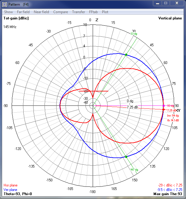
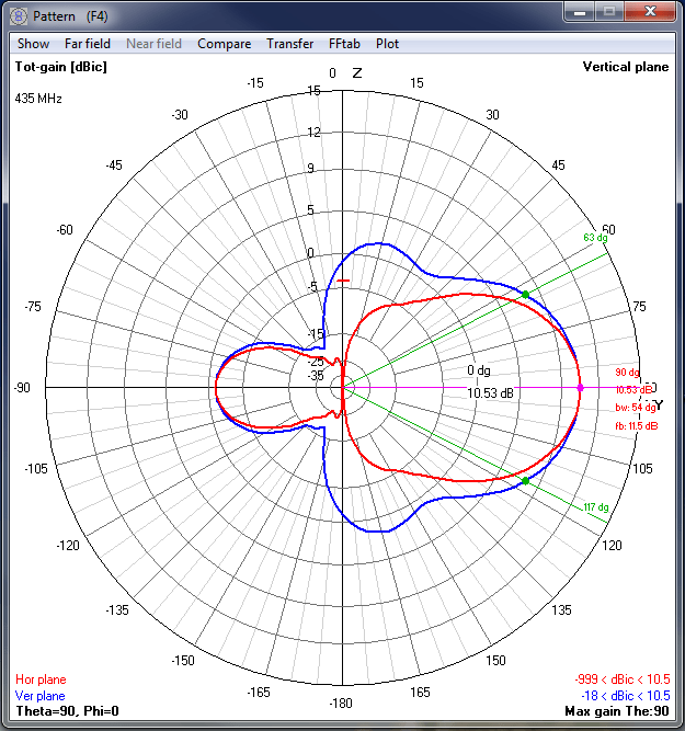
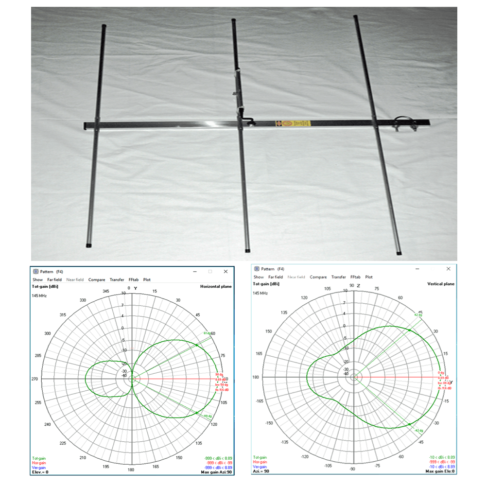
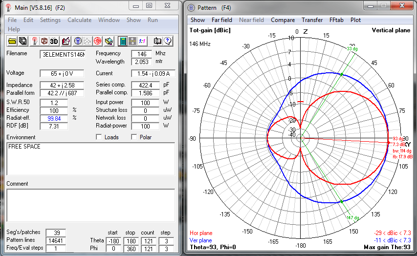
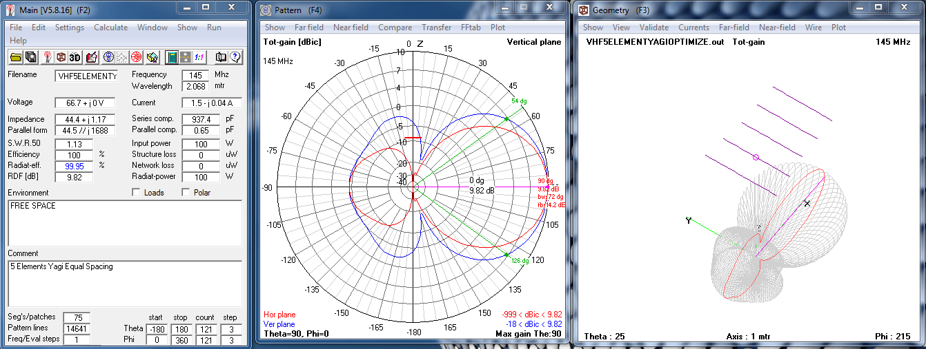
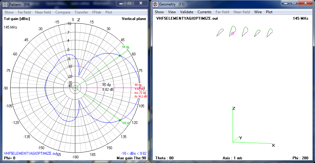
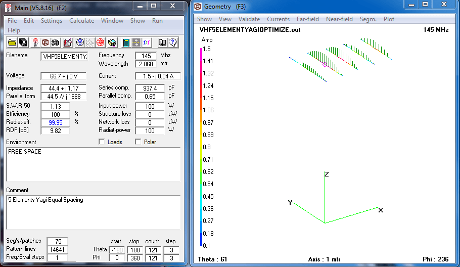
4Nec2 data shows beamwidth, expected pattern and predicted gain.
145Mhz 4NEC2 Data
435Mhz 4NEC2 Data
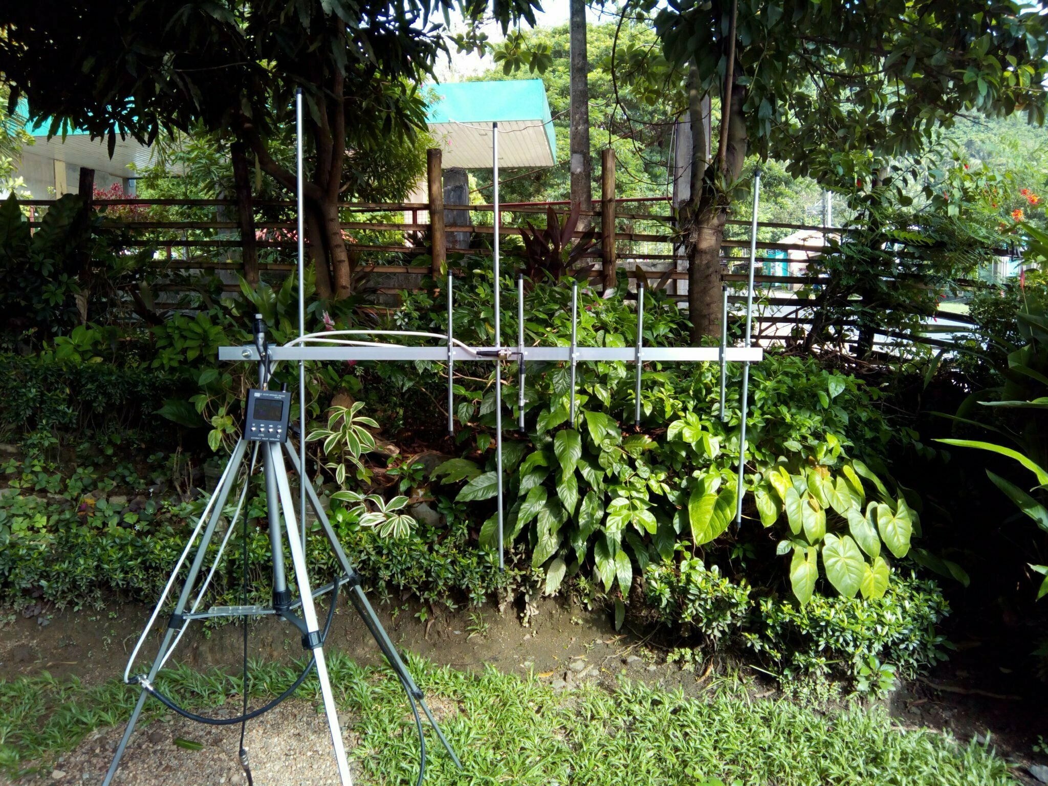
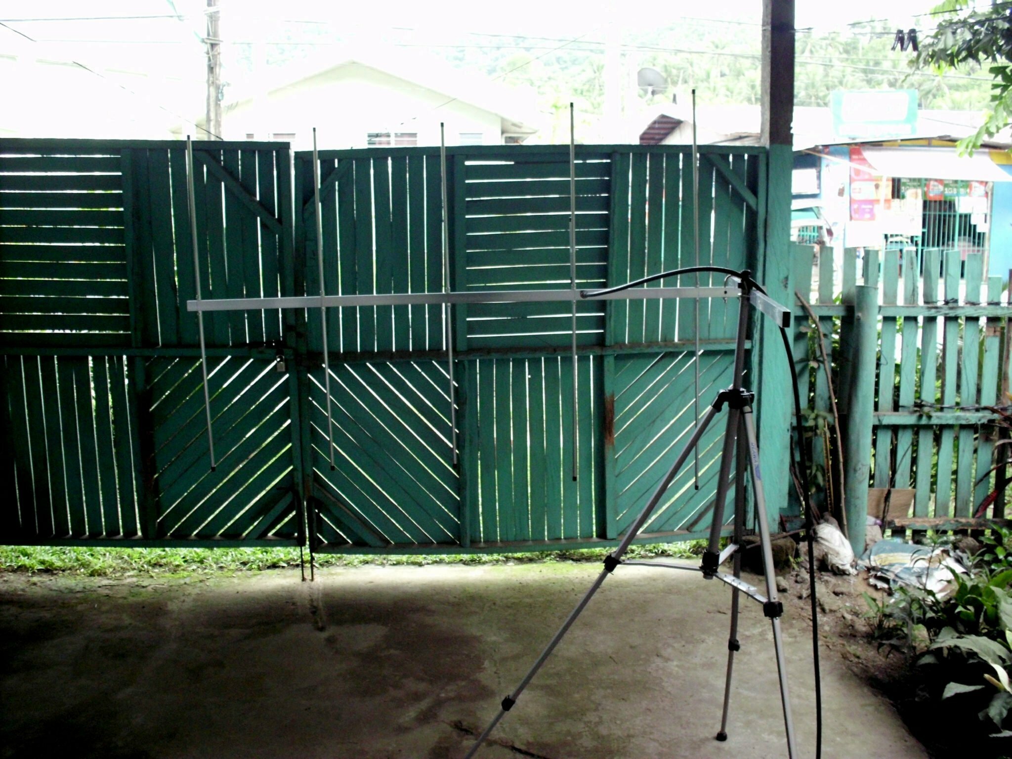
Antenna analyzer measurements and actual video footage
Measurements are taken while holding the antenna and the analyzer since we know that yagi interacts with the actual measurements if it’s too close to an object. This is to simulate the actual use case when using the antenna aiming it to the satellites.
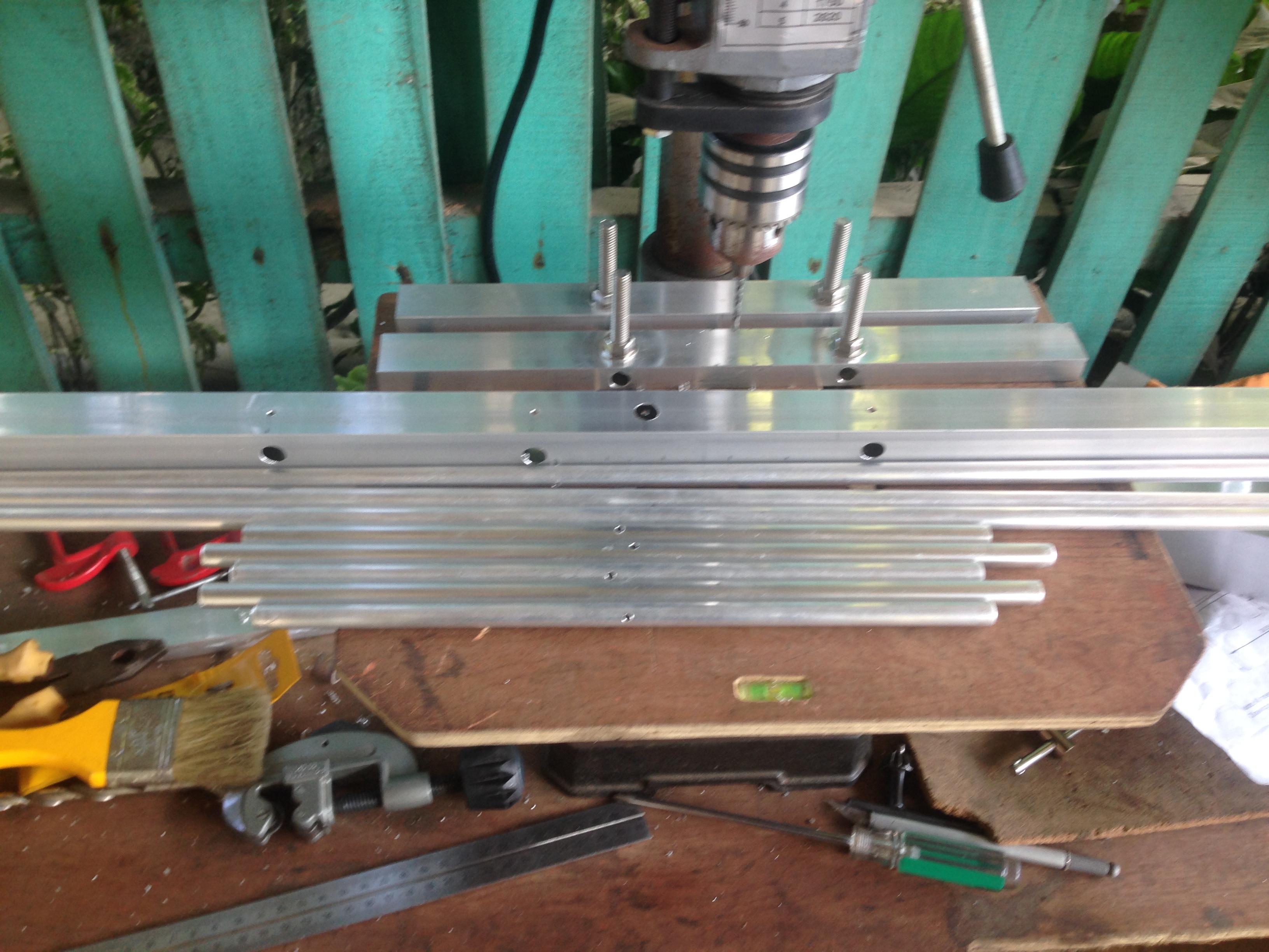
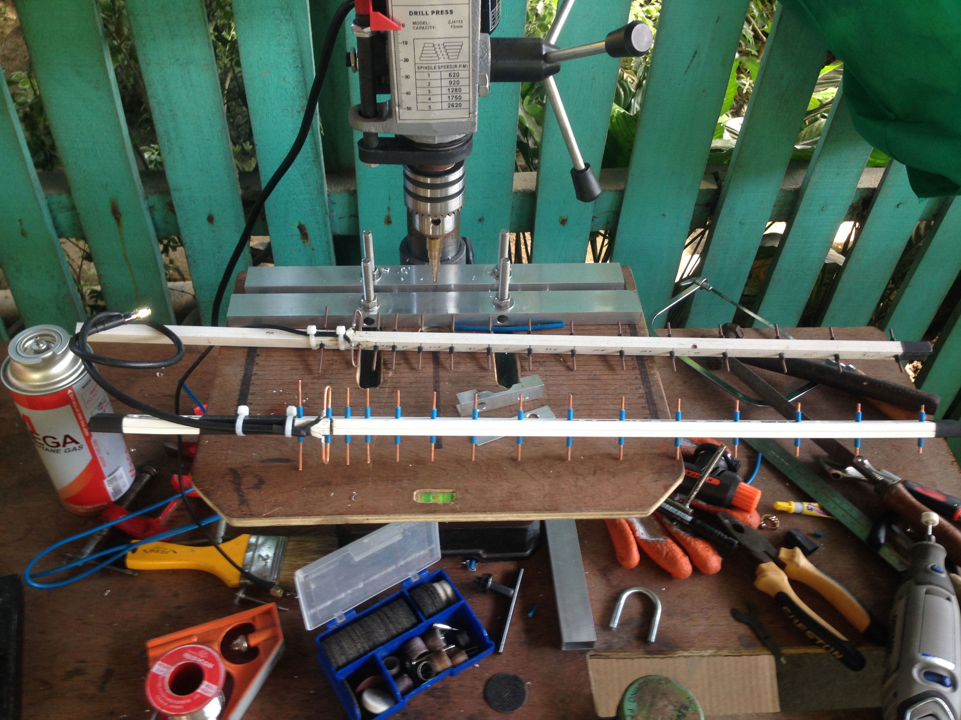
Actual build, measure, cut and drill
These are some photos I took when building the antenna.
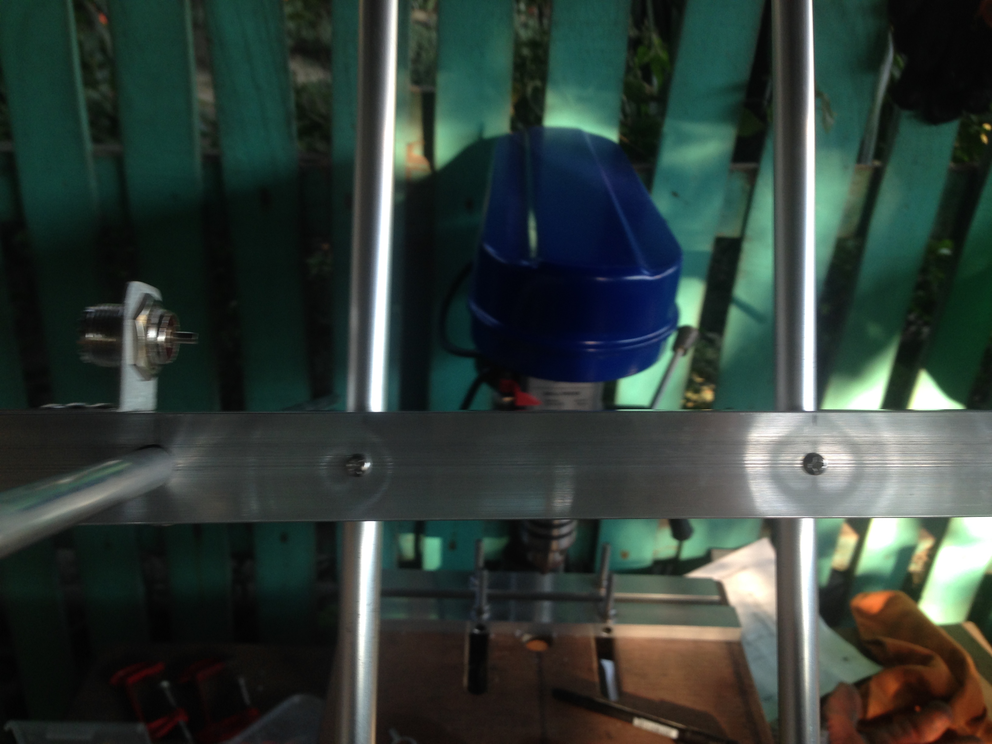
Preparing the materials 3×5 cross yagi and drilling holes.
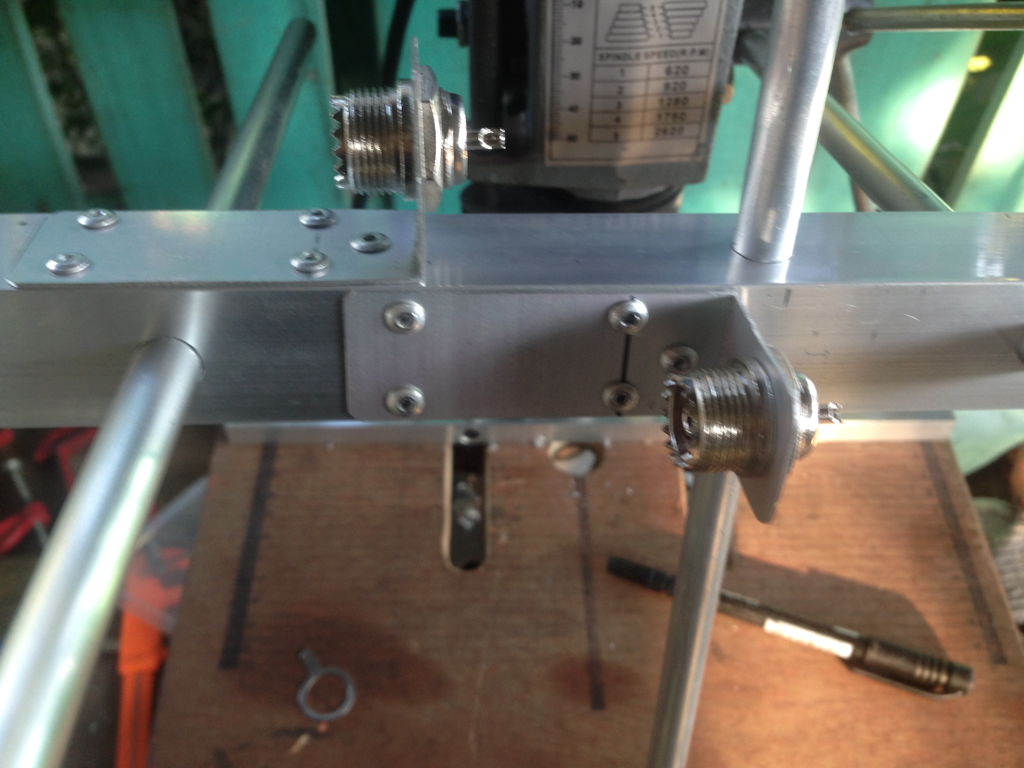
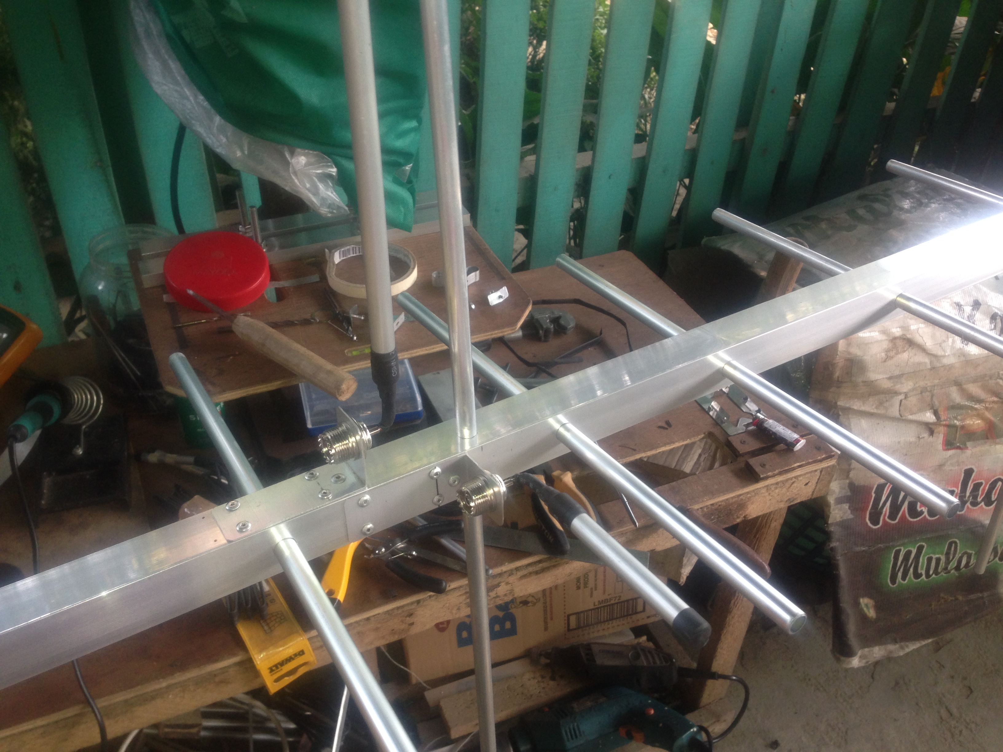
Mounting the elements of the 3×5 cross yagi. Elements are fastened at the center with the screw, chosen so that it just touches the wall of the boom.
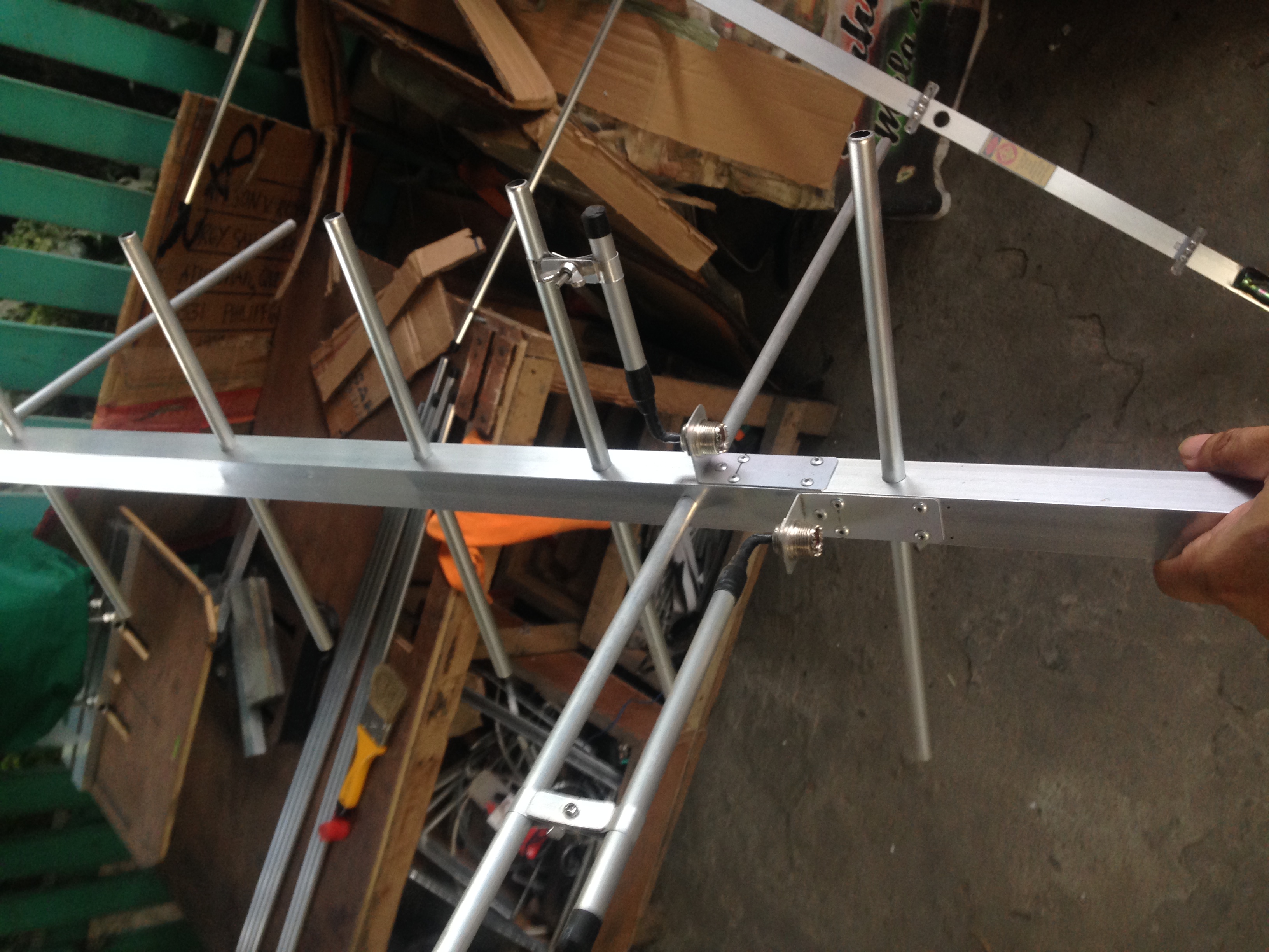
Preparing the feed point. Dual feed point which will connect to the T-connector via phasing harness
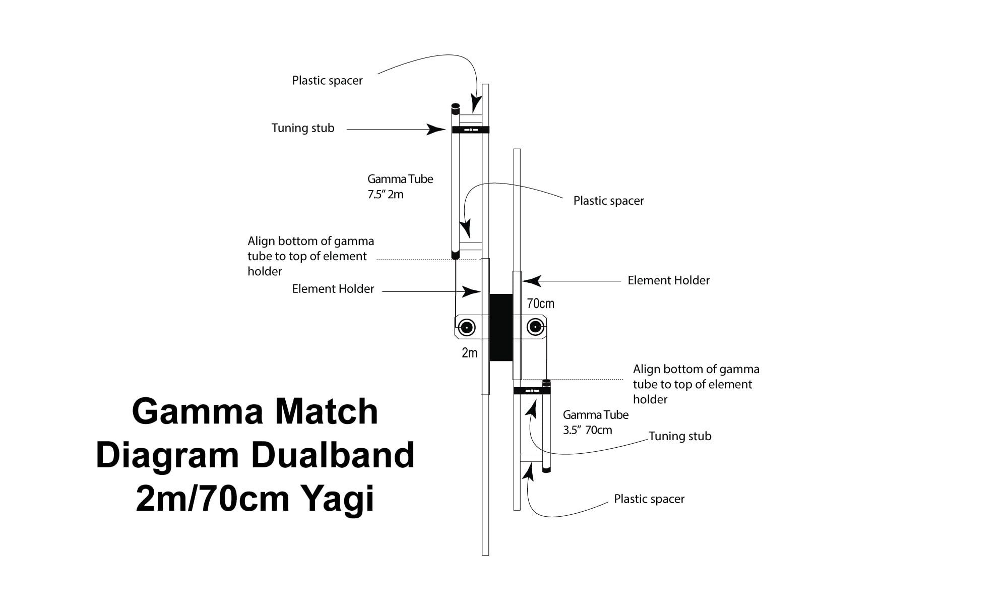
Gamma match preparation which will serve as our feed point for our yagi
Gamma Match final look and feel. The tuning stub are now properly connected to the antenna.
Initial testing of this antenna
I initially test this antenna using a phasing harness of 75ohms at 1/4λ x 3 for the actual length of the harness considering the velocity factor of the coax. The final use case testing, uses 1/4λ x velocity factor for the actual length of the phasing harness.
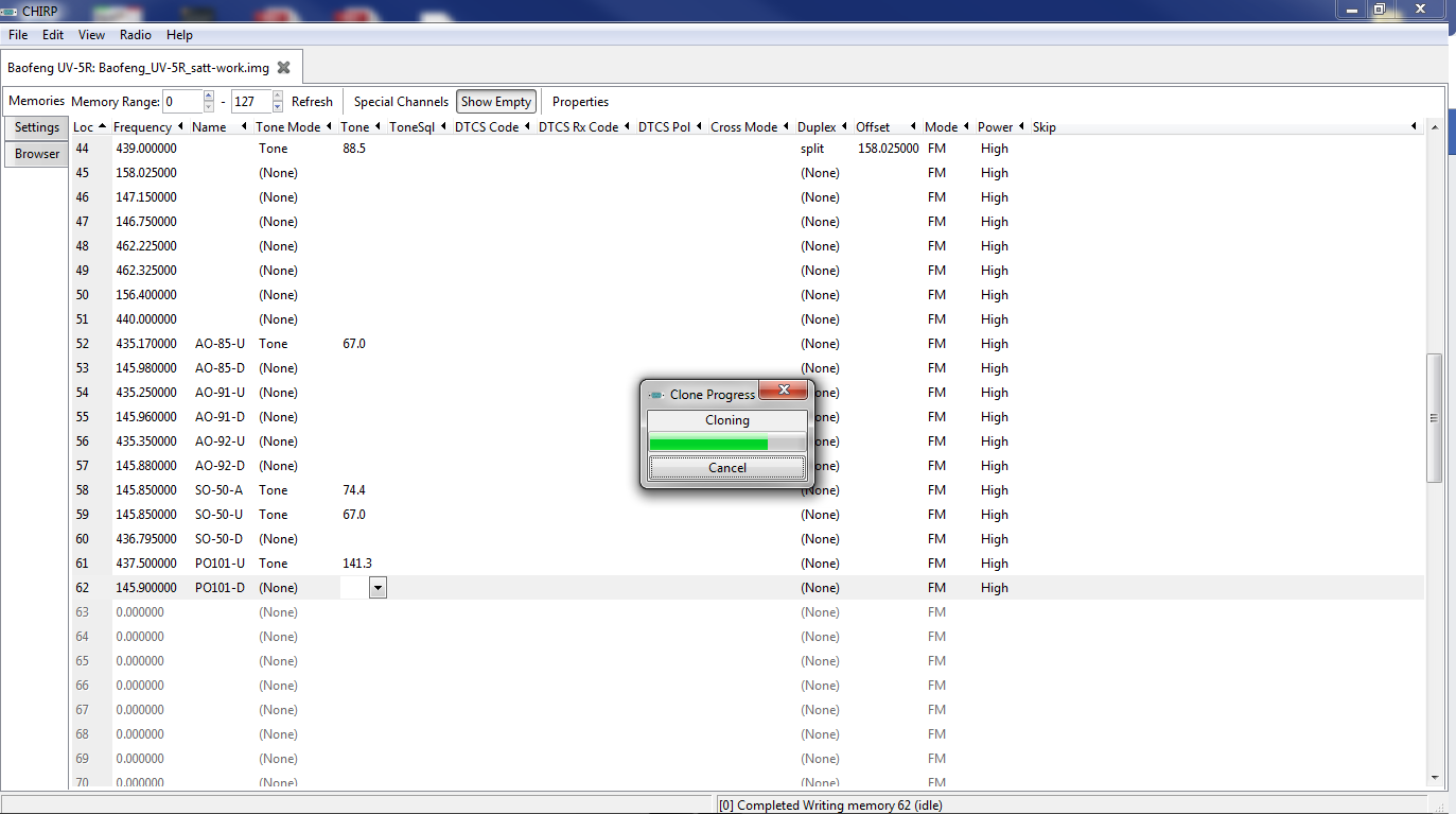
The fun part programming the radio before the hunt
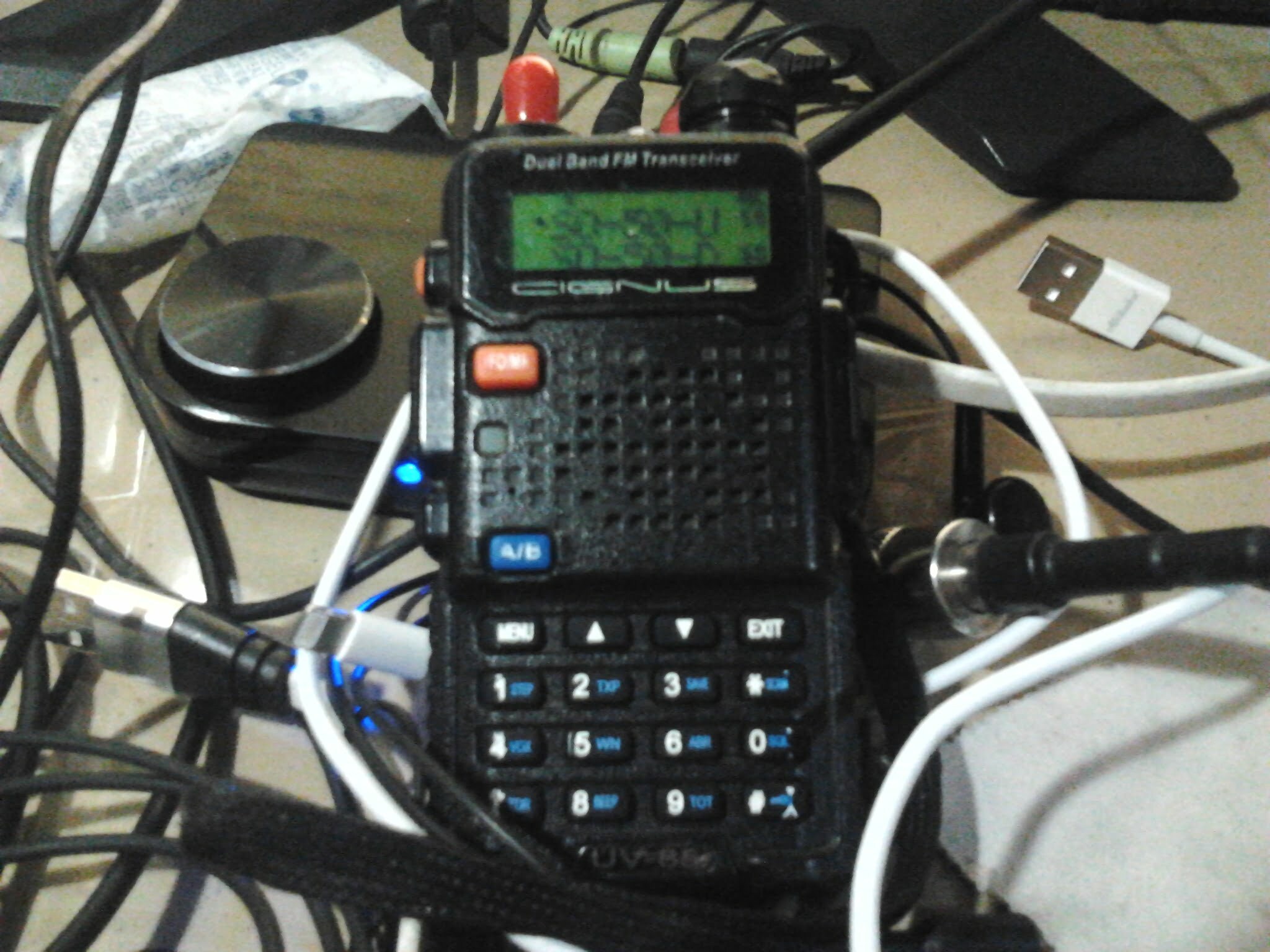
Programming the radio with the satellite frequencies before the actual bird hunting. Since I work on a budget a Baofeng radio will suffice. I used a CIGNUS radio a rebranded radio that uses Baofeng internally ;). I encoded the frequency on the radio using CHIRP taking note of the CTCSS tone for each satellite and marking the channel name as name of the satellite and U for uplink D for downlink and A for arm to trigger some satellite timers before use.
Programming the satellite frequencies before actual hunt. This setup will work on cheap radios for the budget concious ;).
Cignus UV85 a rebranded Baofeng radio which I uses for satellite work. Who say’s you need too expensive gear to work satellites?
Aside from programming the frequencies on your radio you also need a satellite tracker to predict the passes of the satellite you’re hunting. I uses Gpredict which works on both Windows and Linux machines, for Android you may use AmsatDroid Free version and tons of other satellites tracking apps on both Android and IOS.
I use Gpredict for satellite tracking which work on both Windows and Linux machines, because of a very useful interface for predicting satellite passes. You may also use apps on both Android and IOS smart phones
The fun part really start when you begin the hunt and successfully received a very readable reception on your radio coupled with your homebrew antenna. If you’re not familiar with the actual satellite operations listen first until you feel comfortable pressing the PTT on your radio. Satellite resource hog are always frown upon so be courteous every time. Have fun!, and if you feel this will help someone feel free to share, thanks again!
Stacking two antennas – and effects of feed line to a properly tuned antenna
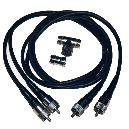
Stacking antenna is done to achieve additional gain ideally a 3dB additional gain is targeted but may not be achievable in real world due to losses introduced by additional cables, you need to make sure that the phasing harness is of the same length and construction. If your cable is not the same length then the signal from those won’t reach the antennas at the same time. The differences may be small but it is enough to create phasing problems, when your signal get to the antenna at two different times they don’t result in a much stronger signal in fact in extreme cases if the signal are exactly 180° degrees out of phase they would cancel each other and you’ll get nothing.
Basic Stacking Requirements
1. Two antenna’s with similar characteristics in terms of Gain: 8.89 dBi Center Frequency: 145Mhz Matching: Gamma Match (Tuning stub) Impedance: 50 ohms Beamwidth: 84° vertical 58°horizontal Front/Back ratio: 11dB SWR: 1:1 @ center frequency
2. Phasing harness – must be of the same length Velocity Factor of coaxial cable accounted for, use two basically identical cables. If the cable types are different, or if the connectors are different, you can have the same phasing problems.
3. Tune the antenna to the lowest possible VSWR match, identically the same response is ideal but a slight mismatch or mis-alignment is acceptable but not much. Your antenna analyzer can help you check this before stacking.
Tuning two stacked Yagi Antenna
Conclusion
A properly matched single antenna, combined with a similar antenna to achieve stacking gain will perform much better than a single antenna, however care must be taken to achieve a good stacking practice. The result of a combined antenna when tested with a good antenna analyzer will result in very little deviation in its Center Frequency , VSWR curve, S11 curve, and Impedance even if different lengths of feed lines are used to test the antenna system.
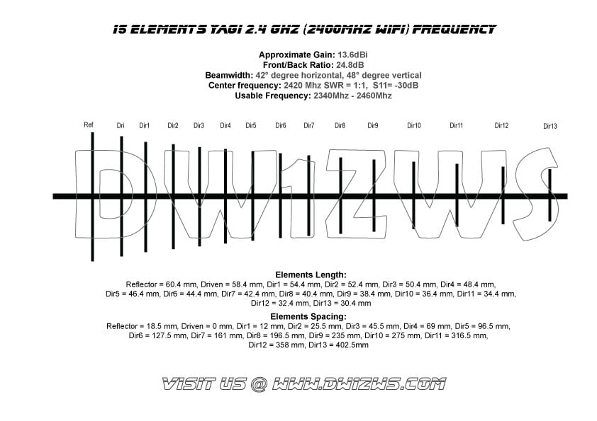
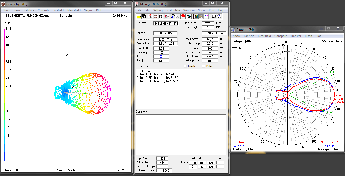
Improving on the design of my 15 Element Yagi Antenna for 2.4Ghz Wifi band, now with a much cleaner pattern no side lobes and higher front to back ratio at 24.8 dB. This antenna is pretty much usable from to 2340 Mhz to 2460 Mhz with less than 2:1 SWR this is centered at 2420Mhz with 1:1 SWR and about -30dB S11 antenna reflection coefficient.
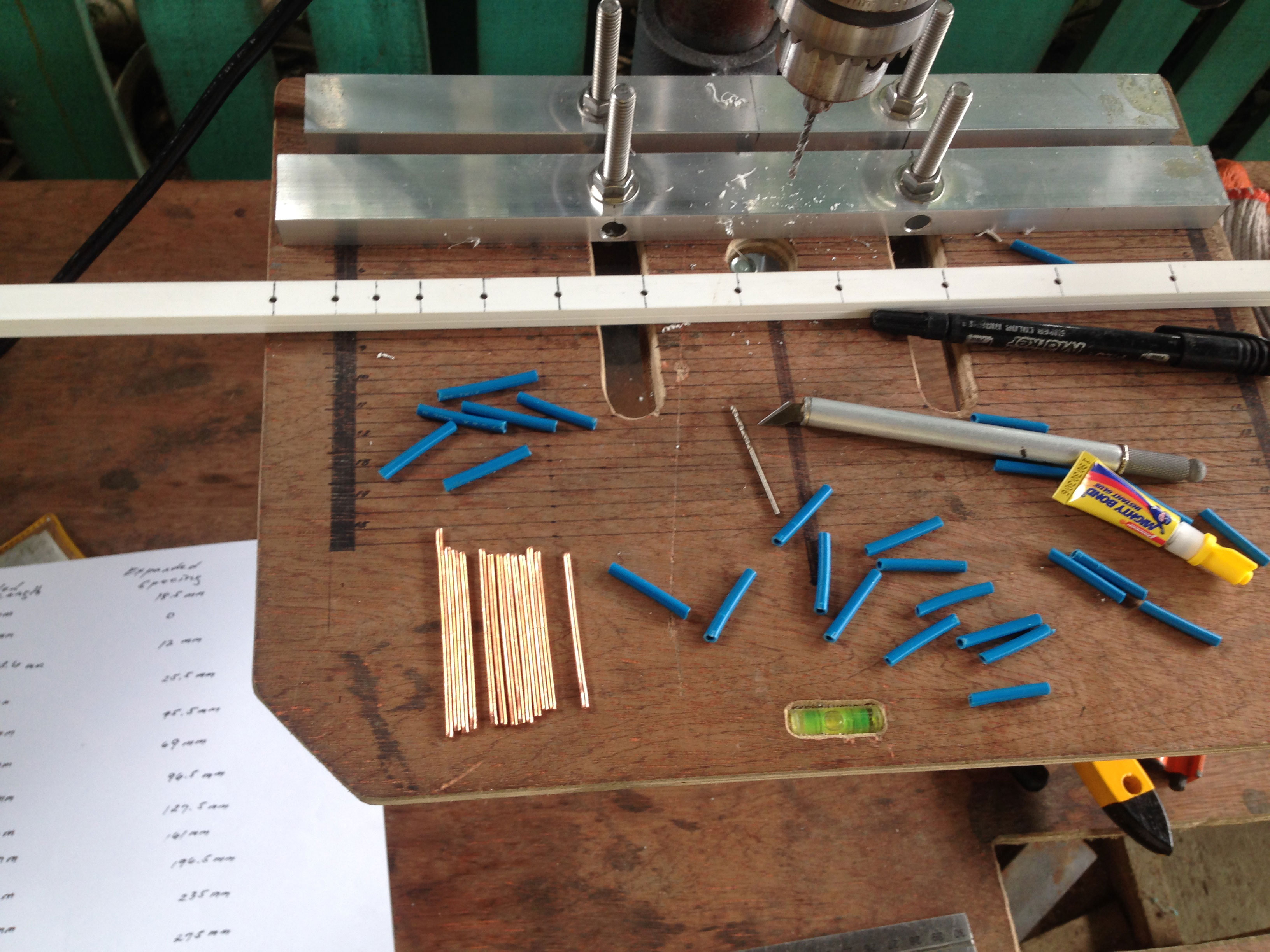
Im still using the same materials to build the antenna
Materials Lists 1. 12mm x 8mm uPvc moulding (Boom) 2. #12AWg solid wire for elements 3. Measuring tool / precision cutter 4. 1 SMA female connector 5. Coaxial cable suitable for SMA connector 6. Sandpaper or file tool for removing rough edges of the elements
Building it is pretty straight forward just cut and paste (lol) bend the driven element and feed it with a 50 ohm coaxial cable rated for WiFi frequency, and check the SWR of the antenna.
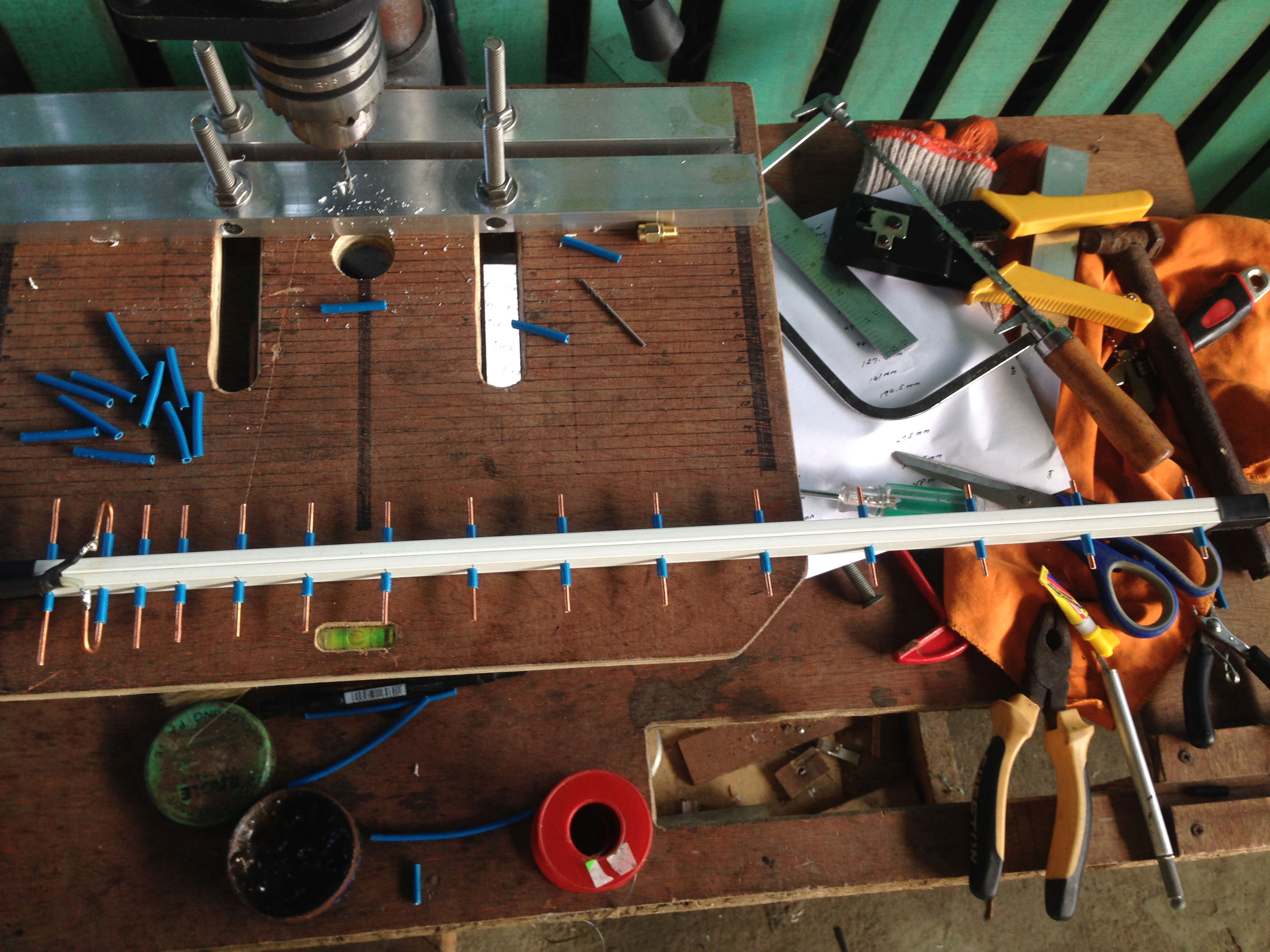
Cut and paste the elements directly to the boom use the wire insulators as fittings to glue on the boom
Here’s the finished antenna side by side with my previous build.
Finished antenna with center frequency at 2.42Ghz
SWR testing video of 15 Element 2.4Ghz yagi antenna
Actual receive analysis and link performance of the yagi antenna
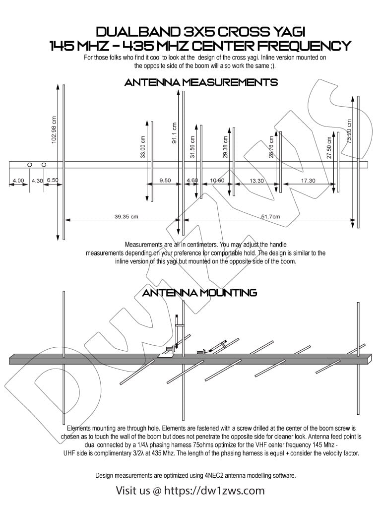
Build your own 2m/70cm 3 Elements VHF by 5 Elements UHF Yagi antenna with excellent gain for both VHF and UHF operation. This antenna is designed for amateur band frequency for both VHF (2m) and UHF (70cm). The antenna has good reflection coefficient and VSWR ratio @ 1.2:1 at center frequency and 1.7:1 at band edge.
Antenna Specs from 4Nec2
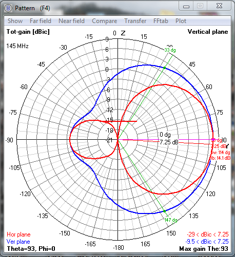
VHF Gain: 7.25dBi @ 145Mhz Beamwidth: 114° degrees Front to Back Ratio: 14.1dB VSWR: 1.0:1
Expected pattern VHF
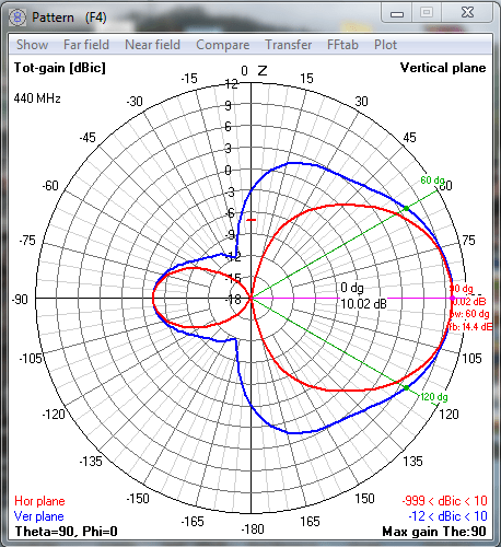
UHF Gain: 10dBi @ 440Mhz Beamwidth: 60° degrees Front to Back Ratio: 14.4dB VSWR: 1.2:1
Expected pattern UHF
Building Video 3 Elements by 5 Elements 2m/70cm Dual band Yagi including Tuning
Material list for 3×5 Elements Dualband Yagi
1. 1″ X 0.5″ Rectangular Aluminum tubing for the boom 2. 3/8″ Aluminum tubing for antenna elements 3. 1cm Outside diameter antenna tubing for elements holder 4. 2pc SO239 connector 5. Pop rivets / Rivet tool 6. #12 AWG Copper wire with insulation (12″for Gamma match) 7. Soldering iron 8. 10pcs Stainless steel nuts and bolts 20mm length 3mm diameter 9. 1pc, Butterfly nut and 1 bolt 18mm length 3mm diameter 10. Aluminum plate 0.5mm thickness 11. 4 X 2″ Aluminum tube for bracket 12. Collapsible tube (shrinkable tubes)
The QYT KY8900 with the cooling fan modification applied. An aluminum tape is applied to closed the gap on the fan so air suction will work more effectively inside the chassis
QYT Modding
QYT KT8900 has good form factor that fits in the palm of your hand. It’s a dual band radio 2m/70cm that supports dual frequency monitoring has an acceptable receiver capability for the price, good audio performance (loud and crispy). Supports FM radio broadcast listening moreover it has a built in repeater function that will work in combination of another QYT KT8900 or pair it with QYT KT8900D by just enabling the function on the menu system and adding a repeater interface cable which can be built easily with spare LAN cable, RJ45 connectors and crimping tool.
If it’s not for the faulty heat sinking then probably this radio will work longer than expected rather than giving up the magic smoke of the RF finals too soon.
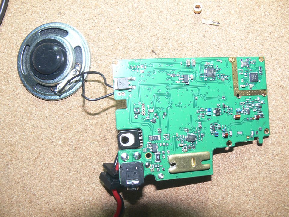
Preparing the RF finals removal and replacement
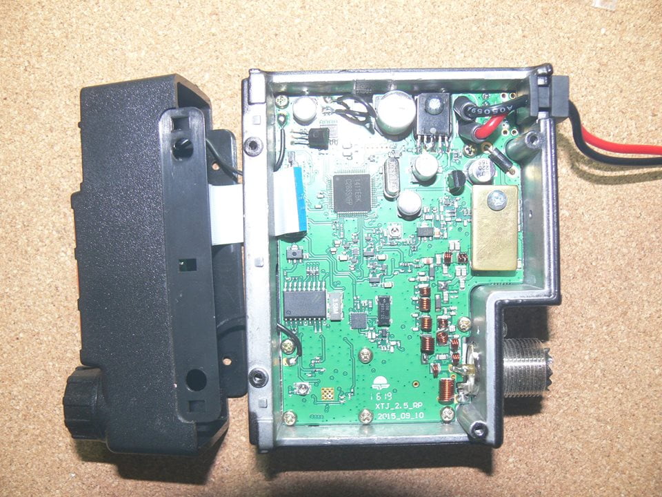
Disassembling the radio to replace the broken RF finals reveals that the screw holding the heat sink is loose just secured by a piece of copper strip inserted to the metal spacer to float the heat sink above the RF finals.
The QYT radio board showing the RF finals when the copper heat sink is removed, also shown is the screw holder with a piece of copper strip used to tighten the loose screw a bit. This copper heat sink is not enough to absorbed the heat coming from the finals and not even touching the aluminum body
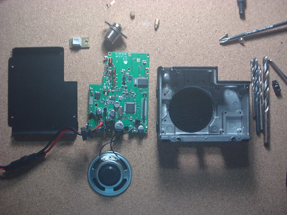
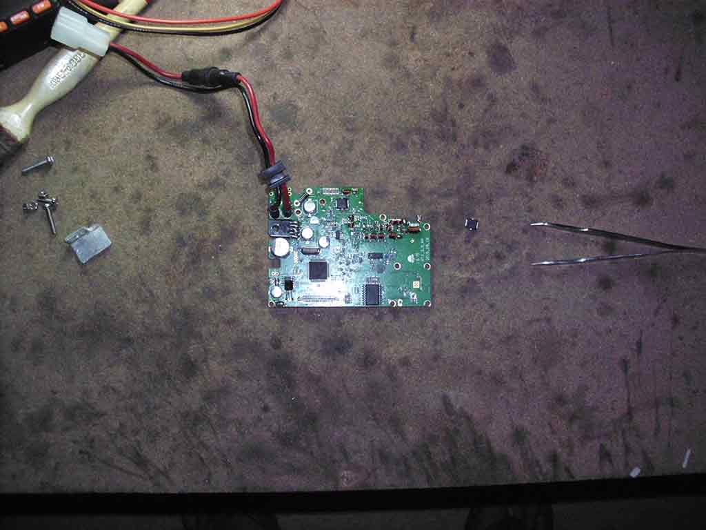
Replacing the RF finals is moderately easy provided you have the right tools a hot air rework station, solder flux, a pair of tweezers. The radio board backside reveals a slightly bigger heat sink which probably is intended to absorbed the heat more effectively by coupling it on the radio chassis, but without using a heat sink compound this also is not too effective to properly address the heat issue.
A much bigger copper heat sink attached at the back of radio board to couple directly to the radio chassis, but QYT didn’t used a heat sink compound to properly transfer the heat to the body.
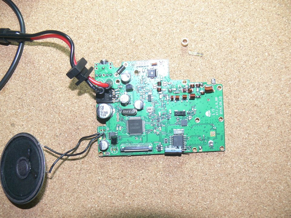
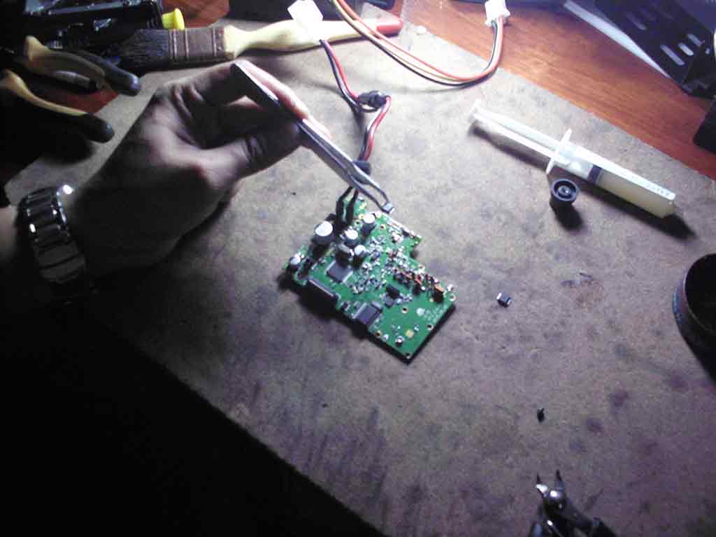
Time to replace the RF finals, apply the solder flux on the chip, heat the board just enough for the solder to melt at the bottom of the RF finals, remember that this is also attached to a copper heat sink below so heating it will take a little longer before you can see that a solder is flowing on the side of the finals. Once removed successfully replaced the finals with a new one. Good news for people living in the Philippines, the RF finals is now available by visiting your favorite electronics store in Gonzalo Puyat street in Sta. Cruz Manila price varies depending on the stores.
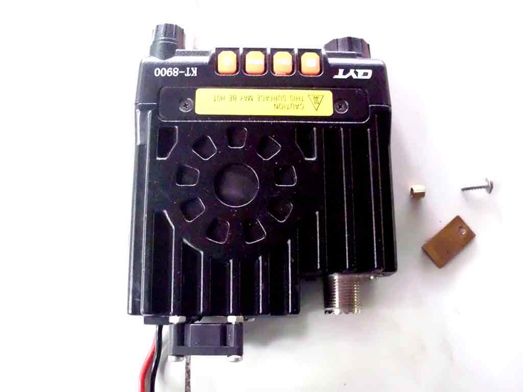
Shown in the picture is the intended aluminum heat sink replacement on top of the QYT RF finals I will attached it directly to the chassis and apply a heat sink compound when finished.
Replacing QYT RF Finals
Replace the RF finals with AFT05M. Preparing the RF finals to be replace. Look for the solder to melt and flow on the side of the finals.
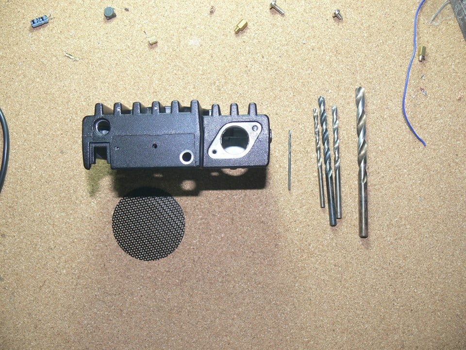
Preparing the fan modification on the radio chassis
Attaching the fan on the radio chassis requires a bit of drilling and tapping to hold the fan securely at the back of the chassis. For QYT KT8900 you can see at the back of the chassis that they somewhat prepared a fan mounting holes, but they didn’t pushed through with the plan. On later versions of this radio a fan is now attached to help in cooling the radio.
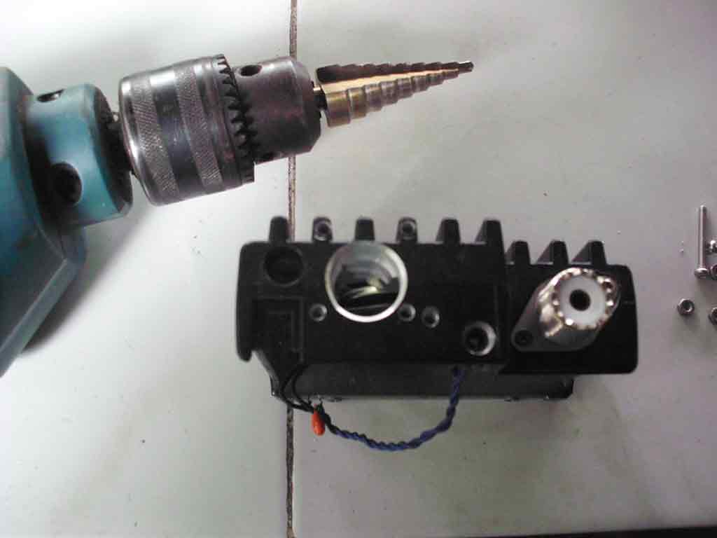
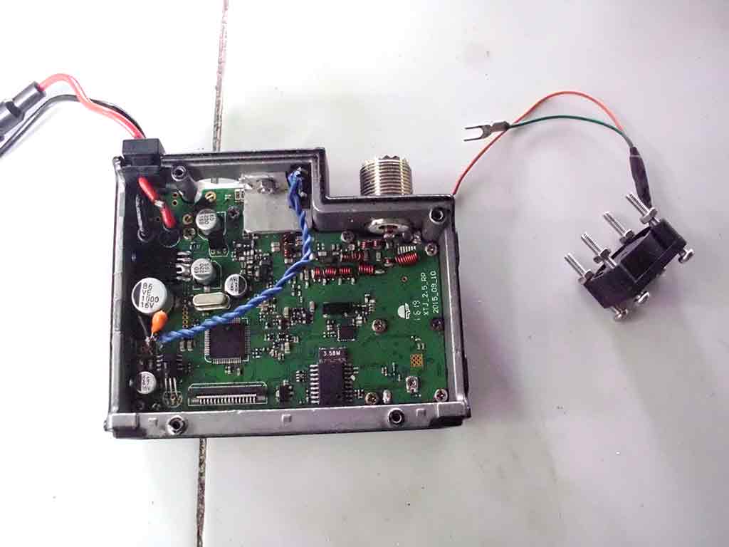
At the back of the radio you can see four holes probably intended for mount the cooling fan. I also added an audio port modification here as this radio doesn’t have a way to attached a headset
Drilling the fan mounting hole with a drill step bit.
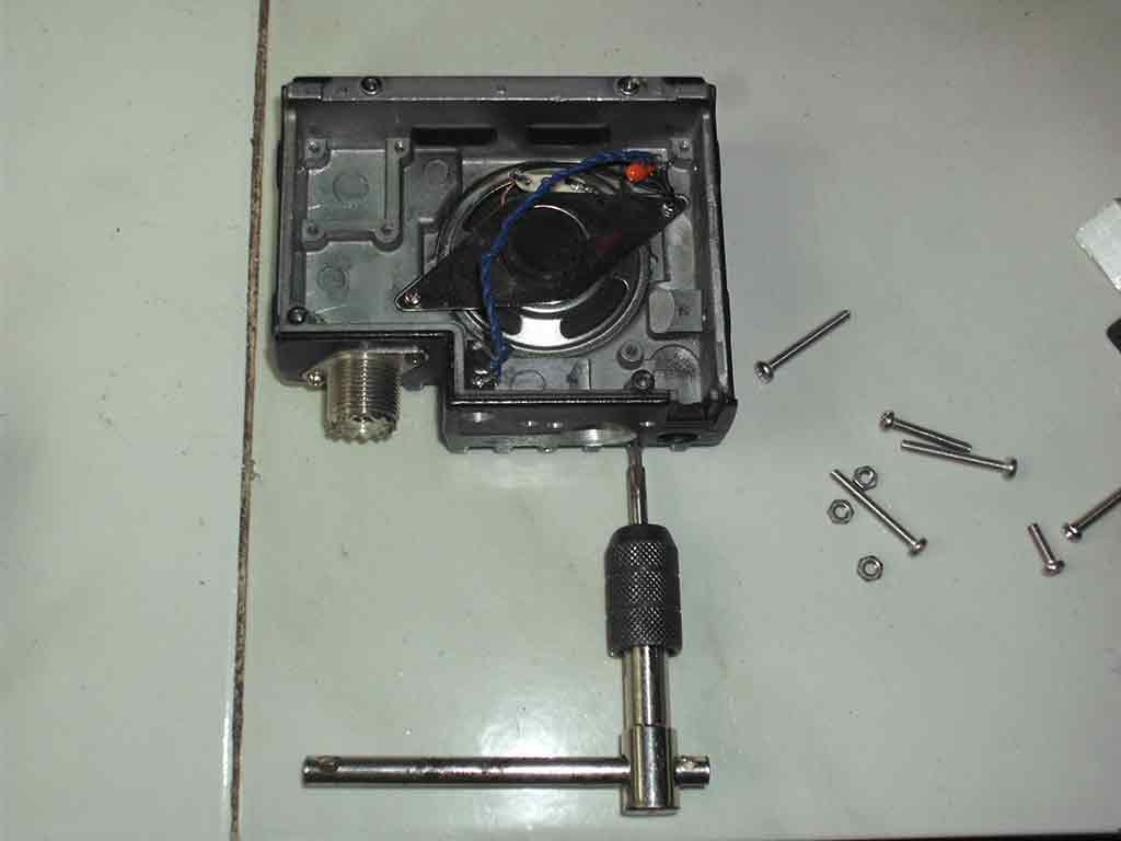
Preparing the screws holder by tapping a thread.
Tapping a thread for the cooling fam I used M3 tap bits for this. Also shown is the wiring going to the audio port this is attached to the speaker point on the board.
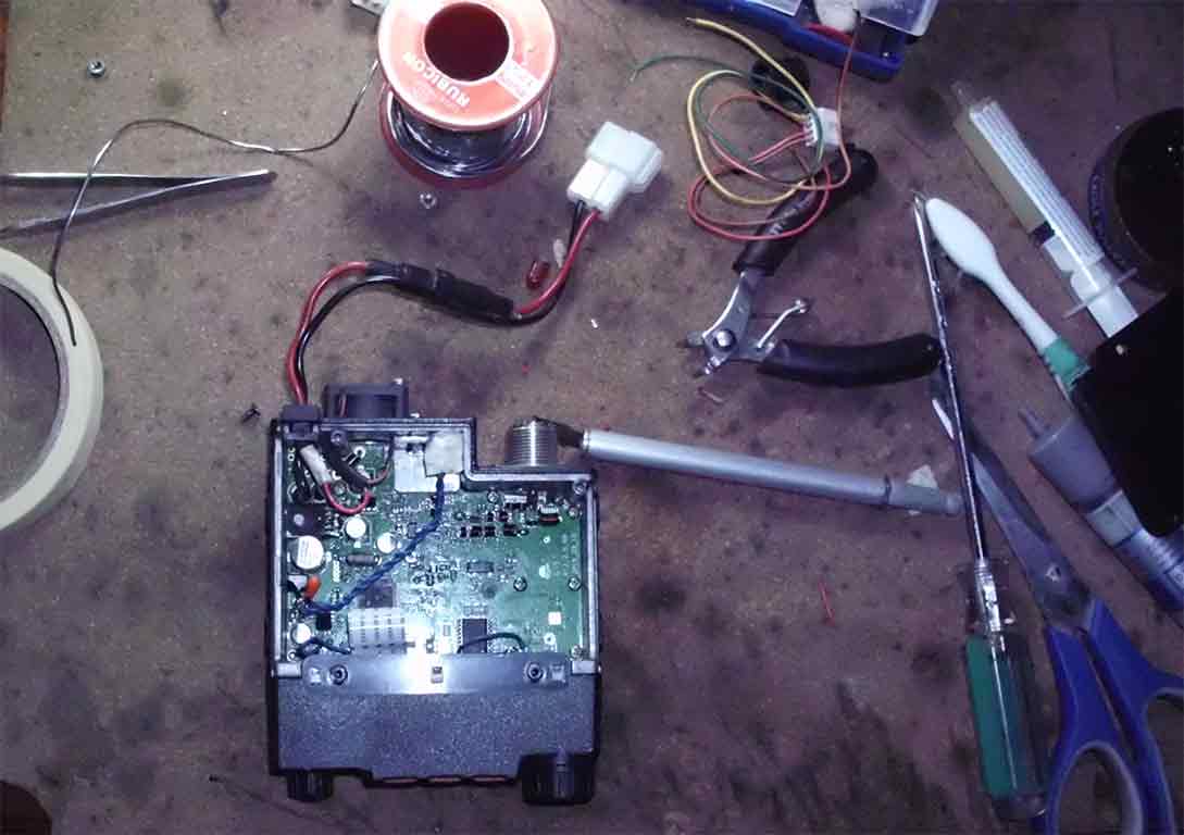
Putting it back together.
The cooling fan is ready for mounting on the chassis. The heat sink is attached firmly on the chassis. Heat sink mounting compound is applied at the bottom of the chassis and at the side holding the heat sink.
The cooling fan is now mounted on the chassis. The heat sink is attached firmly on the radio chassis. Heat sink mounting compound is applied at the bottom of the chassis and at the side holding the heat sink.
Finally the finished modification applied to the radio.
The QYT KT8900 radio with the cooling fan attached at the back, the old heat sink removed and replaced with a new one.
The final look and successful cooling fan modification.
The QYT KY8900 with the cooling fan modification applied. An aluminum tape is applied to closed the gap on the fan so air suction will work more effectively inside the chassis
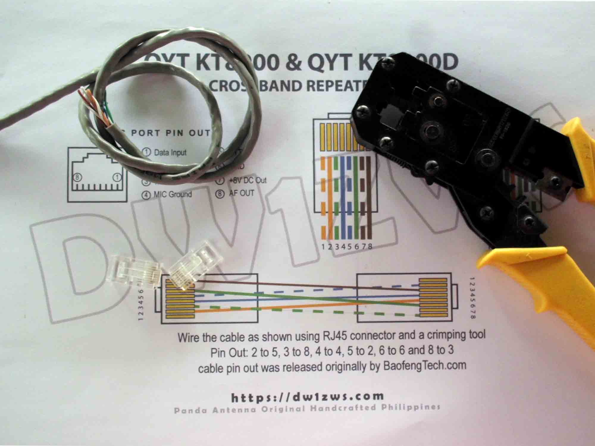
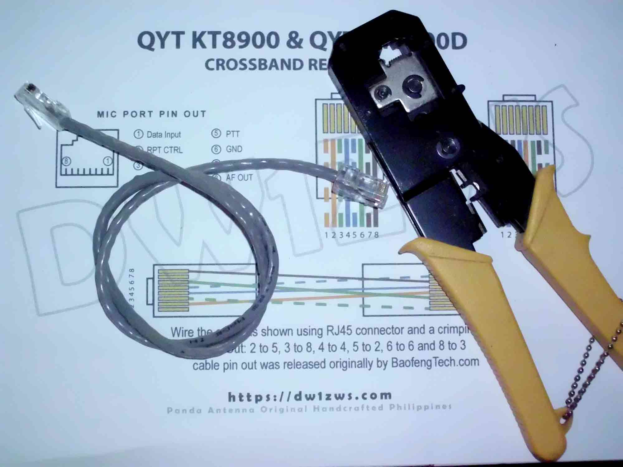
QTY KT8900 and QYT KT8900D chinese radios and variants have a built in repeater function that works out of the box without additional modification on the radio. You just need to enable the repeater function (cross band repeater VHF/UHF or UHF/VHF) via the menu system. Connect the two radios via the mic port using the cable shown here and enable the repeater function on the radio. The radios will work in the repeater mode cross band and will re-transmit your audio either on the VHF or UHF and vice versa.
The repeater interface will work on the variants of these radios in either combination of at least 2 KT8900 RX/TX, 2 KT8900D RX/TX or 1 KT8900 and 1 KT900D and of course Baofeng Tech radios. The configuration is done on individual radios by setting the REP-M (Repeater transponder function on both radio). Once a matched Carrier, CTCSS/DCS, TONE or DTMF is received in either of the radios it will re-transmit the audio on the other radio and vice versa.
The repeater interface will work on the variants of these radios in either combination of at least 2 KT8900 RX/TX, 2 KT8900D RX/TX or 1 KT8900 and 1 KT900D and of course Baofeng Tech radios. The configuration is done on individual radios by setting the REP-M (Repeater transponder function on both radio). Once a matched Carrier, CTCSS/DCS, TONE or DTMF is received in either of the radios it will re-transmit the audio on the other radio and vice versa.
Build the cable
Do it yourself using RJ45 modular connector and a piece of LAN UTP cable
DIY X-Band Repeater Cable for KT8900 and 8900D and variants
Finished Cross Band X-Band repeater interface
Let’s see how it works
Testing video of working repeater system
Features
1. Easy deployment for field work to extend portable radio range with acceptable results 2. Will fit easily in a go box 3. Inexpensive but it works
Caveats
1. Recommended for light usage as QYT Radios tend to heat up easily 2. Use the upgraded version of QYT the KT8900D for more stability 3. Suitable only for Cross Band configuration 3. KT 8900 heats up like a barbecue grill if it didn’t burn your finals at least bring a hotdog to grill …
1″ X 0.5″ Rectangular Aluminum tubing for the boom 3/8″ Aluminum tubing for antenna elements 1cm Outside diameter antenna tubing for elements holder 1pc SO239 connector Pop rivets / Rivet tool #12 AWG Copper wire with insulation (12″for Gamma match) Soldering iron 6pcs Stainless steel nuts and bolts 20mm length 3mm diameter 1, Butterfly nut and 1 bolt 18mm length 3mm diameter Aluminum plate 0.5mm thickness Collapsible tube (shrinkable tubes)
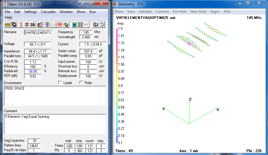
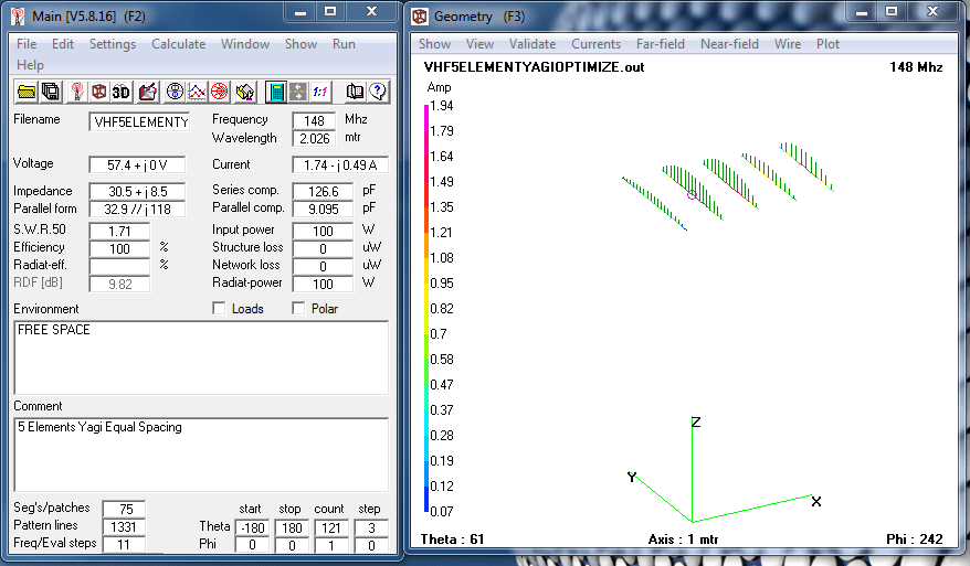
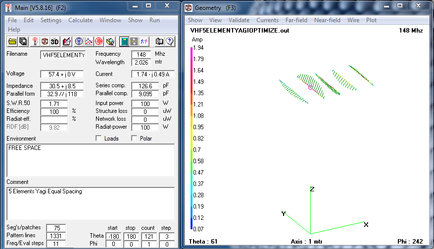
Antenna Patterns
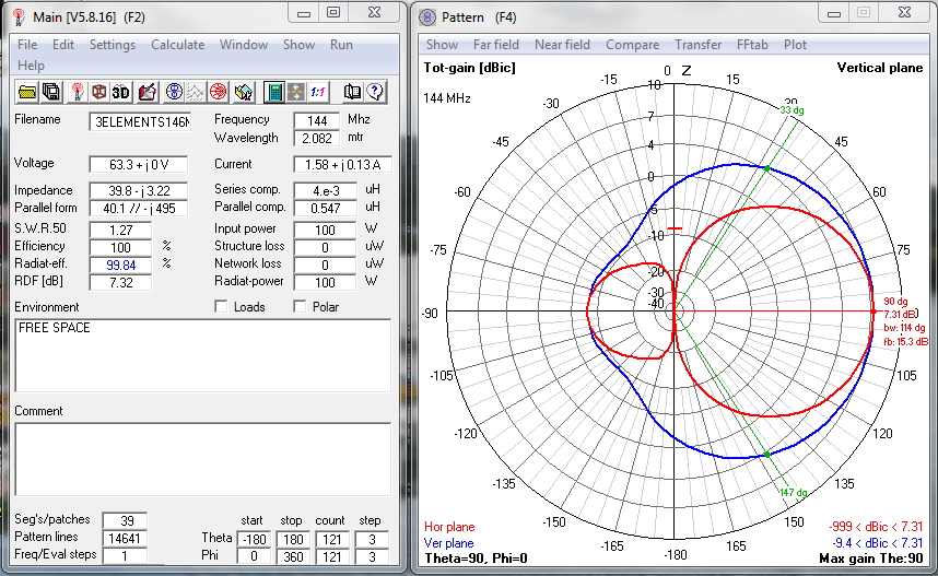
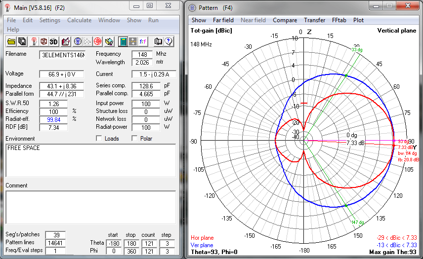
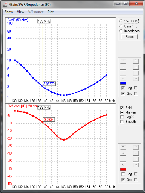
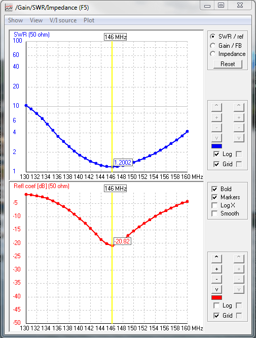
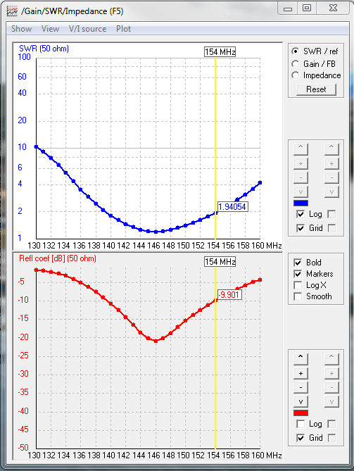
To check the antenna pattern and expected gain if the antenna will perform similarly on other bands these are the results with both slight increased in SWR and little decreased in gain on 144Mhz and 148Mhz respectively but the expected pattern are generally the same. I’m using 4NEC2 for antenna simulation and analysis.
Predicted antenna pattern for 146MhzPredicted antenna pattern for 144MhzPredicted antenna pattern for 148MhzPredicted VSWR 140MhzPredicted VSWR 146MhzPredicted VSWR 154Mhz
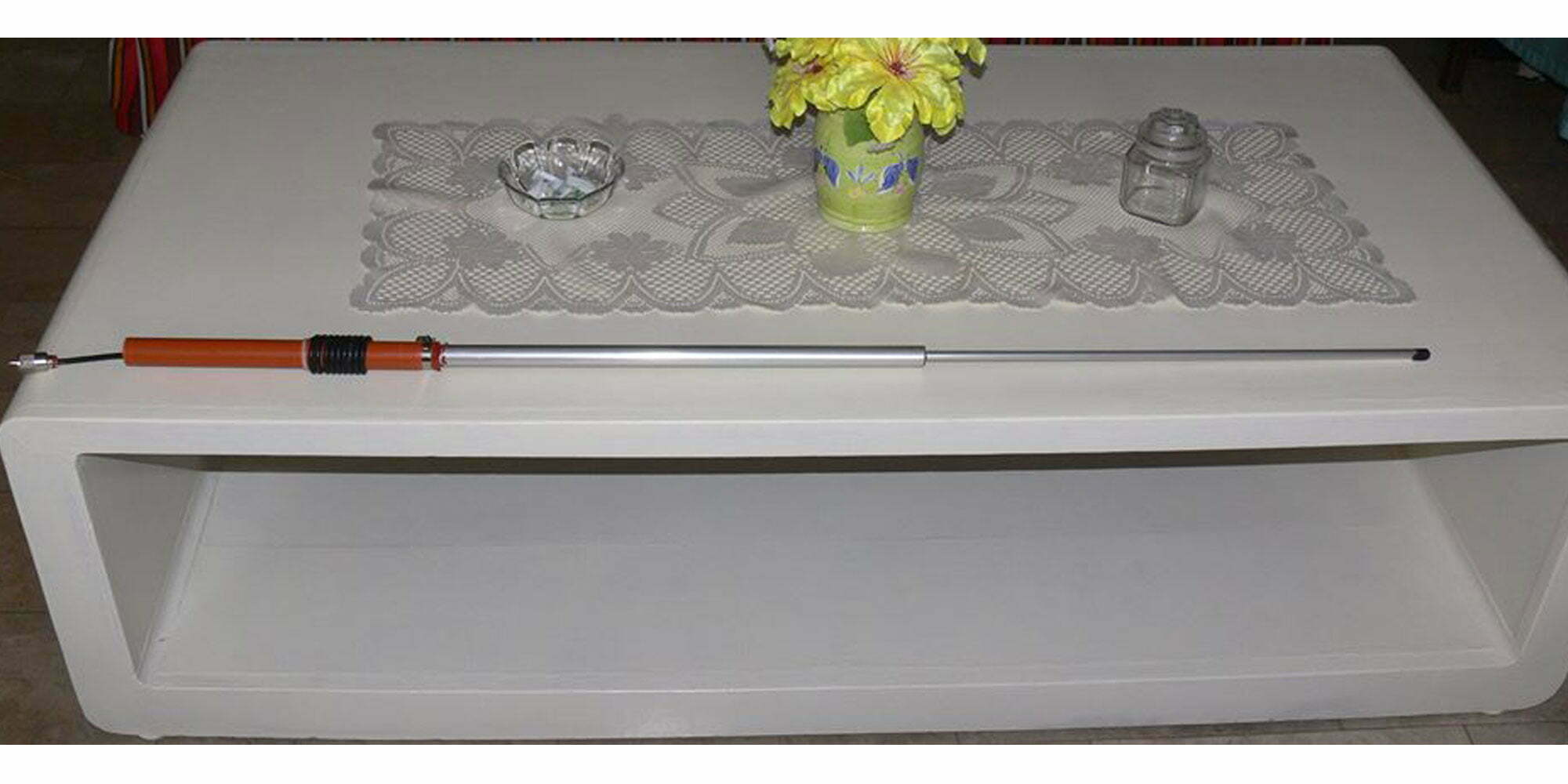
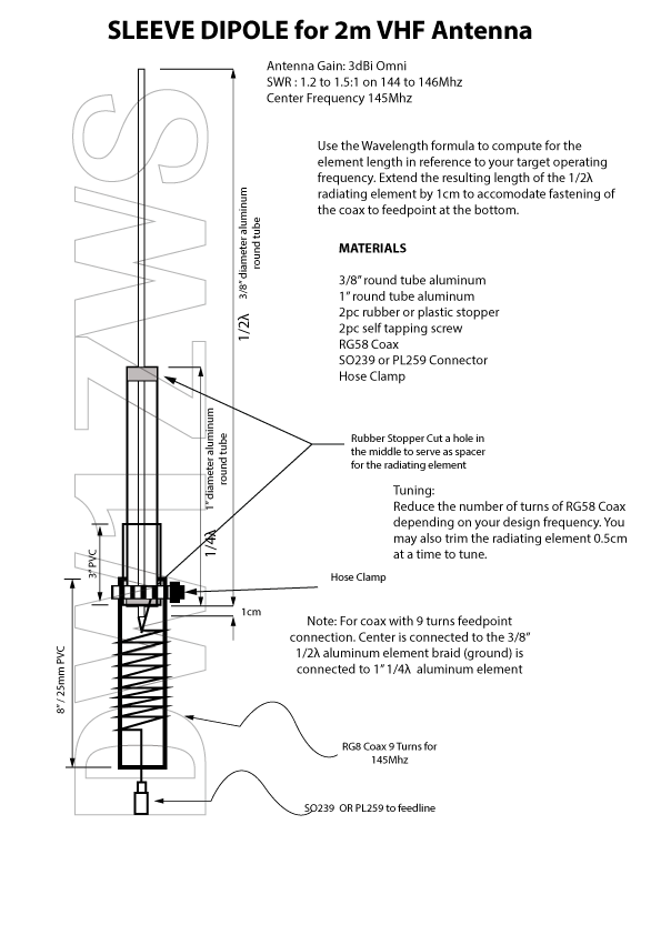
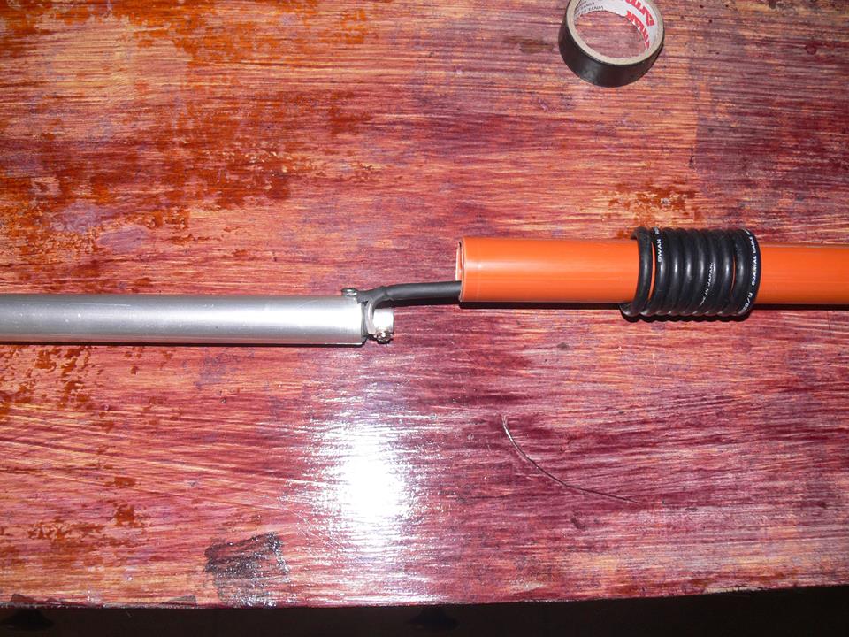
Sleeve Dipole Antenna Build a 2m VHF lightweight sleeve dipole antenna. A compact portable antenna and easy for deployment. You can even operate the dipole while holding it. Building it is easy just follow the antenna plans below. The antenna specifications are below including the testing video.
Antenna Gain: 3dBi Pattern: Omni Features: Lightweight and Portable easy deployment
We use cookies on our website to give you the most relevant experience by remembering your preferences and repeat visits. By clicking “Accept”, you consent to the use of ALL the cookies.
This website uses cookies to improve your experience while you navigate through the website. Out of these, the cookies that are categorized as necessary are stored on your browser as they are essential for the working of basic functionalities of the website. We also use third-party cookies that help us analyze and understand how you use this website. These cookies will be stored in your browser only with your consent. You also have the option to opt-out of these cookies. But opting out of some of these cookies may affect your browsing experience.
Necessary cookies are absolutely essential for the website to function properly. These cookies ensure basic functionalities and security features of the website, anonymously.
Cookie
Duration
Description
cookielawinfo-checkbox-analytics
11 months
This cookie is set by GDPR Cookie Consent plugin. The cookie is used to store the user consent for the cookies in the category "Analytics".
cookielawinfo-checkbox-functional
11 months
The cookie is set by GDPR cookie consent to record the user consent for the cookies in the category "Functional".
cookielawinfo-checkbox-necessary
11 months
This cookie is set by GDPR Cookie Consent plugin. The cookies is used to store the user consent for the cookies in the category "Necessary".
cookielawinfo-checkbox-others
11 months
This cookie is set by GDPR Cookie Consent plugin. The cookie is used to store the user consent for the cookies in the category "Other.
cookielawinfo-checkbox-performance
11 months
This cookie is set by GDPR Cookie Consent plugin. The cookie is used to store the user consent for the cookies in the category "Performance".
viewed_cookie_policy
11 months
The cookie is set by the GDPR Cookie Consent plugin and is used to store whether or not user has consented to the use of cookies. It does not store any personal data.
Functional cookies help to perform certain functionalities like sharing the content of the website on social media platforms, collect feedbacks, and other third-party features.
Performance cookies are used to understand and analyze the key performance indexes of the website which helps in delivering a better user experience for the visitors.
Analytical cookies are used to understand how visitors interact with the website. These cookies help provide information on metrics the number of visitors, bounce rate, traffic source, etc.
Advertisement cookies are used to provide visitors with relevant ads and marketing campaigns. These cookies track visitors across websites and collect information to provide customized ads.