Categories
Antenna Plans

Building the Gamma Match for 3 Elements Yagi

So you’ve decided to build the 3 Elements Yagi, you’ve checked all the diagrams and tutorial video on building the Yagi. You decided that everything is easy, except on how would you proceed in building the gamma match. Sure the tutorial video is enticing however it seems not clear on how things would fit in the context of the gamma match assembly.

So what is a gamma match in the context of the driven element and why should we use it?.

A gamma match is an adjustable device used for feeding and matching an antenna, coupled to the driven element of a beam to match the 50 ohm coaxial feed-line.

The gamma accomplishes 3 things:

1. Usually it’s a small diameter wire parallel and in close vicinity with the main radiating element, it will carry only a fraction of the main element current while being exposed to the same electrical field strength. This turns it in an effective up-transformer of the antenna input impedance. A sort of folded dipole performing an impedance step up.

2. It forms together with the main radiating element a closed wire stub, adding inductance to the antenna input impedance. If it is not required for matching, this additional inductance can be cancelled out with a lumped capacitor in series. A parallel shorted transmission line stub, adding shunt inductance.

3. The sheath of the coaxial feed-line (braid) is connected to the center of the main radiating element. When properly connected, a gamma-match also serves as a balanced to unbalanced converter or balun.

A note of caution: This gamma match would work only on the specified antenna design. Since this is a matching assembly you need to adjust it to your specific design if you happen to re-purpose it for other antenna project. Probably it’s one of the reason why most of the available design on the internet provides only the elements measurements (antenna matching is a subject for experimentation).

Download a PDF Printable document here

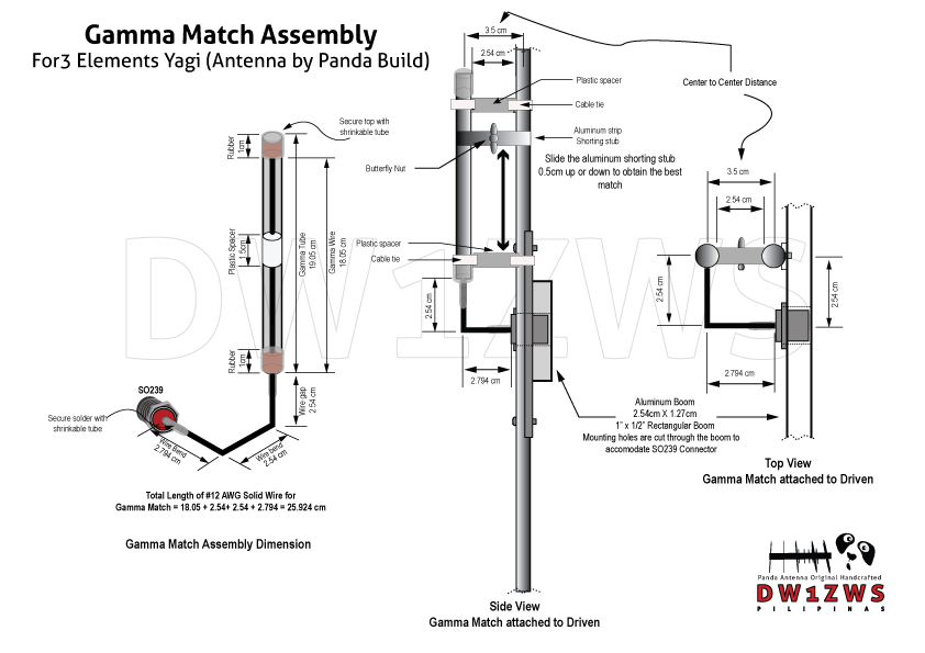
Materials for our 3 Elements Yagi Gamma Match

1. A piece of #12AWG solid wire (refer to diagram for actual measurements at least 12″ cut accordingly)
2. A piece of 3/8 aluminum tubing for gamma tube (see diagram for actual measurement)
3. 1pc SO239 Connector and 1.5cm round plastic insulator (the center insulator of RG8 coaxial cable is suitable)
4. 1pc Butterfly nut and 1pc bolt 18mm length 3mm diameter
5. Aluminum plate 0.5mm thickness (cut to strip length of 1 25.4cm x 1cm adjust accordingly for shorting stub)
6. Rubber stopper 1cm thickness for both ends of gamma tube
7. Soldering iron and soldering lead to solder the piece of wire to SO239
8. Collapsible tube (shrinkable tubes) for securing the ends of gamma match assembly.
9. Plastic spacer (a 1.2cm rectangular plastic wire conduit is suitable uPVC moldings)
10. 2pcs of aluminum plates measuring 2.54cm in length and 1cm thickness (use a piece of boom to make one, use it to sandwich the aluminum strip and secure it with the butterfly nut)
11. Cable tie to secure plastic spacer.

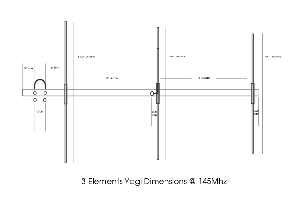
To build the gamma match, cut the required materials as seen on the diagram. Insert the round plastic spacer to the middle of solid wire and put a rubber stopper at both ends of the gamma tube. You need to cut a hole in the middle of the bottom rubber stopper to facilitate inserting the wire to the gamma tube. Bend the wire to the actual measurement in the diagram and solder the SO239 connector to the wire. Secure the gamma match assembly using the shrinkable tube to make it water tight. Put the plastic spacer in between the driven element and the gamma match and secure it with the cable tie. Finally attach the gamma match to driven element and and sandwich the shorting stub with 2pcs aluminum plates and secure it with the butterfly nut. Use the shorting stub to tune your antenna.

Categories
Antenna Plans

Build a 4 Elements Yagi

Material list for building a 4 Elements Yagi

  1. 1″ X 0.5″ Rectangular Aluminum tubing for the boom
  2. 3/8″ Aluminum tubing for antenna elements
  3. 1cm Outside diameter antenna tubing for elements holder
  4. 1pc SO239 connector
  5. Pop rivets / Rivet tool
  6. #12 AWG Copper wire with insulation (12″for Gamma match)
  7. Soldering iron
  8. 8pcs Stainless steel nuts and bolts 20mm length 3mm diameter
  9. 1, Butterfly nut and 1 bolt 18mm length 3mm diameter
  10. Aluminum plate 0.5mm thickness
  11. Collapsible tube (shrinkable tubes)

Download Yagi Dimensions Here

To build the 4 Elements Yagi you may follow the direction for building the 3 Elements Yagi except that you will add an additional parasitic element (director) which is about 5% shorter than the last element of the 3 elements yagi. The spacing are the same between the elements and when built successfully it will give you a very desirable 9.39dBi gain or about or about 7.24dBd.

To increase the performance you may also configure the antenna in stack configuration by making two antenna’s and connect it with a phasing harness for increased performance.

Antenna Gain Simulation and Signal Pattern Using 4Nec2 antenna modeling.

Front to Back Ratio: 9.92dB
Antenna Gain: 9.39dBi
Beamwitdh: 70° Vertical 54° Horizontal

Vertical Pattern 4 Elements Yagi
Horizontal Pattern 4 Elements Yagi
Combined pattern 4 Elements Yagi
Categories
Antenna Plans

3 Elements Yagi Lightweight End Mount (Antenna by Panda Build)

Building a Lightweight End Mount 3 Elements Yagi

Building a high performance 3 Elements lightweight end mount Yagi antenna. The awesome Yagi antenna provides many advantages in a number of applications.This antenna has high gain allowing lower strength signals to be received. Yagi antenna has better directivity which enables interference levels to be minimized and have straight forward construction i.e; the Yagi antenna allows all constructional elements to be made from rods simplifying construction. The construction enables the antenna to be mounted easily on vertical and other poles with standard mechanical fixings.

3 Elements Yagi Antenna Materials List

1″ X 0.5″ Rectangular Aluminum tubing for the boom
3/8″ Aluminum tubing for antenna elements
1cm Outside diameter antenna tubing for elements holder
1pc SO239 connector
Pop rivets / Rivet tool
#12 AWG Copper wire with insulation (12″for Gamma match)
Soldering iron
6pcs Stainless steel nuts and bolts 20mm length 3mm diameter
1, Butterfly nut and 1 bolt 18mm length 3mm diameter
Aluminum plate 0.5mm thickness
Collapsible tube (shrinkable tubes)

3 Element Yagi making, tuning and testing video

Measurements

1 Boom Length 80 cm (Use rectangular aluminum tubing)
Reflector Element (length) = 103.7cm
Driven Element (length) = 98.9cm
Director Element length) = 91.8cm

Spacing

Antenna Pattern and Gain from 4Nec2 Simulation

Antenna Data

Horizontal Pattern
Vertical Pattern
Average ground Performance

Testing Performance of 3 Elements Yagi inside the room

What can you say about this article and video tutorial, leave your comment on the comment box!

Categories
Amateur Radio

Contact with the North using 5 Elements VHF/UHF Dualband Yagi

Las Piñas to Lupao Nueva Ecija using 5 Elements VHF/UHF Dualband Yagi modulation with Manong Charlie and Manong Leopard from Lupao Nueva Ecija at 144.200Mhz. Dualband Yagi designed by Panda Antenna TX signal is 5 by 4 using Yaesu 2900R at 60watts power output (no booster) a total of 151.61kms air distance and receiving at 5 by 3, 5 by 2, typical reciprocity in signal strength.

Categories
Antenna Plans

Edison Fong – Tri-Band Antenna without Radials

Performance should be comparable to a dipole and should operate on a single feed line. Tri-Band antenna for 2Meters, 1.25Meters, and 70 Centimeters.

Download here

Categories
Antenna Plans

Edison Fong (DBJ-2) J Pole Roll Up

Dual band 2 meter / 70 cm J-pole antenna a practical, easy to replicate, “roll-up” portable antenna.

Download here

Categories
Antenna Plans

Edison Fong – (DBJ-1) J Pole Antenna

High performance inexpensive dual band antenna for VHF and UHF

Download here

Categories
Amateur Radio

Coaxial Cable Attenuation Charts

A compilation of some of the most common coaxial cable attenuation. Nominal attenuation of 30.5 meters (100ft)

Cable Type70-85 Mhz148-174 Mhz400-520 Mhz806-960 Mhz2.4-2.45 Ghz5.8-5.85 Ghz
RG178B/U12.4 dB17.0 dB30.4 dB40.8 dB
RG1799.2 dB11.5 dB17.0 dB22.3 dB
RG174/U7.8 dB10.8 dB19.2 dB26.9 dB
RG58C/U4.6 dB7.1 dB13.5 dB18.2 dB
CELLFOAM ™4.1 dB5.6 dB9.8 dB13.2 dB
CELLFOIL ™2.8 dB4.2 dB6.9 dB9.0 dB
RG142B/U3.3 dB4.9 dB8.9 dB12.0 db
RG223/U4.2 dB5.7 dB10.0 dB13.7 dB
RG59B/U3.1 dB4.9 dB9.0 dB13.2 dB
RG62A/U2.3 dB3.4 dB5.9 dB8.0 dB
RG11/U1.8 dB2.5 dB4.8 dB5.6 dB
RG213/U2.0 dB2.6 dB5.0 dB7.4 dB
RG214/U1.9 dB2.6 dB5.0 dB7.4 dB
10D-FB Type0.9 dB1.2 dB2.4 dB3.1 dB
RG8 Type1.2 dB1.7 dB3.1 dB4.5 dB7.0 dB10.6 dB
1/4″ Superflex1.3 dB2.2 dB4.2 dB5.6 dB9.9 dB15.8 dB
3/8″ Superflex1.1 dB1.5 dB2.8 dB3.8 dB6.9 dB10.9 dB
1/2″ Superflex0.8 dB1.3 dB2.4 dB3.4 dB5.9 dB10.2 dB
1/4″ HELIAX ®1.1 dB1.5 dB2.7 dB3.6 dB5.8 dB11.2 dB
3/8″ HELIAX ®0.9 dB1.3 dB2.3 dB3.3 dB5.7 dB9.5 dB
1/2″ HELIAX ®0.6 dB0.8 dB1.6 dB2.2 dB3.7 dB5.9 dB
7/8″ HELIAX ®0.3 dB0.5 dB0.9 dB1.3 dB2.3 dB
7/8″ HELIAX ®0.3 dB0.4 dB0.8 dB1.1 dB2.0 dB
7/8″ HELIAX ®0.3 dB0.4 dB0.9 dB1.2 dB2.1 dB
13″ HELIAX ®0.2 dB0.3 dB0.6 dB0.9 dB1.6 dB
1θ” HELIAX ®0.2 dB0.3 dB0.5 dB0.7 dB1.4 dB

Coaxial Cable Attenuation Ratings
Nominal attenuation dB/100 feet at (Mhz)

RG/U CABLE1.01050100200400900100030005000
6A,2120.260.831.92.74.15.96.59.823.0032.00
8 MINI,8X1.12.53.85.47.98.813.026.0
LMR-2400.240.761.72.43.44.97.57.914.218.7
8,8A,10A,2130.150.551.31.92.74.17.58.016.027.00
9913,9086,90960.91.41.82.64.24.513.00
4XL8IIA,FLEXI 4XL0.91.41.82.64.24.513.00
LMR-4000.91.22.54.14.3
LMR-5000.71.02.03.23.4
LMR-6000.60.81.42.52.7
82140.601.21.72.74.27.814.222.0
90951.01.82.63.86.07.5
9,9A,9B,2140.210.661.52.33.35.07.88.818.027.0
11,11A,12,12A,13,13A,2160.190.661.62.33.34.87.816.526.5
14,14A,2170.120.411.01.42.03.15.512.419.0
17,17A,18,18A,218,2190.60.240.620.951.52.44.49.515.3
55B,2230.31.23.24.87.010.014.316.530.546.0
580.331.23.14.66.910.514.517.537.560.0
58A,58C0.441.43.34.97.412.020.024.054.083.0
59,59B0.331.12.43.44.97.011.012.026.542.0
62,62A,71A,71B0.250.851.92.73.85.38.38.718.530.0
62B0.310.902.02.94.26.211.024.038.0
141,141A,400,142,142A0.300.902.13.34.76.913.026.040.0
1742.33.96.68.912.017.528.230.064.099.0
178B,196A2.65.610.514.019.028.046.085.0100
188A,3163.16.09.611.414.216.731.060.082.0
179B3.05.38.510.012.516.024.044.064.0
393,2350.61.42.13.14.57.514.021.0
4021.22.73.95.58.013.026.026.0
40522.0
LDF4-50A0.060.210.470.680.981.42.22.34.35.9
LDF5-50A0.030.110.250.360.530.781.21.42.53.5
Categories
Amateur Radio

Power Loss at Various SWR readings and Residual Power

SWR (Standing Wave Ratio) affects the power output of your radio. The following table shows the effect of SWR for a transmitter with 100 watts of transmitted power.

SWR Reading% Of LossEff. Radiated PowerPower Output in WattsPower Loss in Watts
1.0:10.0%100.0%100.000.0
1.1:10.2%99.8%99.80.2
1.2:10.8%99.2%99.20.8
1.3:11.7%98.3%98.31.7
1.4:12.8%97.2%97.22.8
1.5:14.0%96.0%964
1.6:15.3%94.7%94.75.3
1.7:16.7%93.3%93.36.7
1.8:18.2%91.8%91.88.2
2.0:111.1%88.9%88.911.1
2.2:114.1%85.9%85.914.1
2.4:117.0%83.0%8317.0
2.6:119.8%80.2%80.219.8
3.0:125.0%75.0%7525
4.0:136.0%64.0%6436
5.0:144.4%55.6%55.644.4
6.0:151.0%49.0%4951
7.0:156.3%43.8%43.856.3
8.0:160.5%39.5.0%39.560.5
9.0:164.0%36.0%3664
10.0:166.9%33.1%33.166.9

To compute your useful output power into the antenna, read your output power, and multiply it by the ERP percentage above, using your SWR reading.

Example: If your transceiver output is 75.0 Watts, and the VSWR is 1.5. From the table above 1.5:1 the radiating efficiency is 96.0% percent. Simply multiply 75.0 Watts by 0.96 (96/100 to decimal). The result is 72.0 Watts.

Categories
Amateur Radio Schematics

Schematic Diagram QYT KT8900_M (Ver: 1.0)

Schematic diagram for QYT KT8900 Juentai JT-6188 aka MP300, 8900mini
VHF / UHF Compact Mobile Frequency Range 136-174 / 400-480 MHz

Download here

Download RF finals datasheet here