
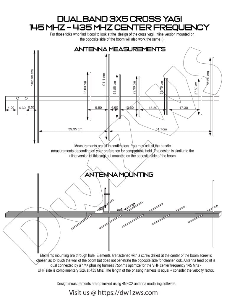
Dualband 3×5 cross yagi 145Mhz – 435Mhz
Materials preparation
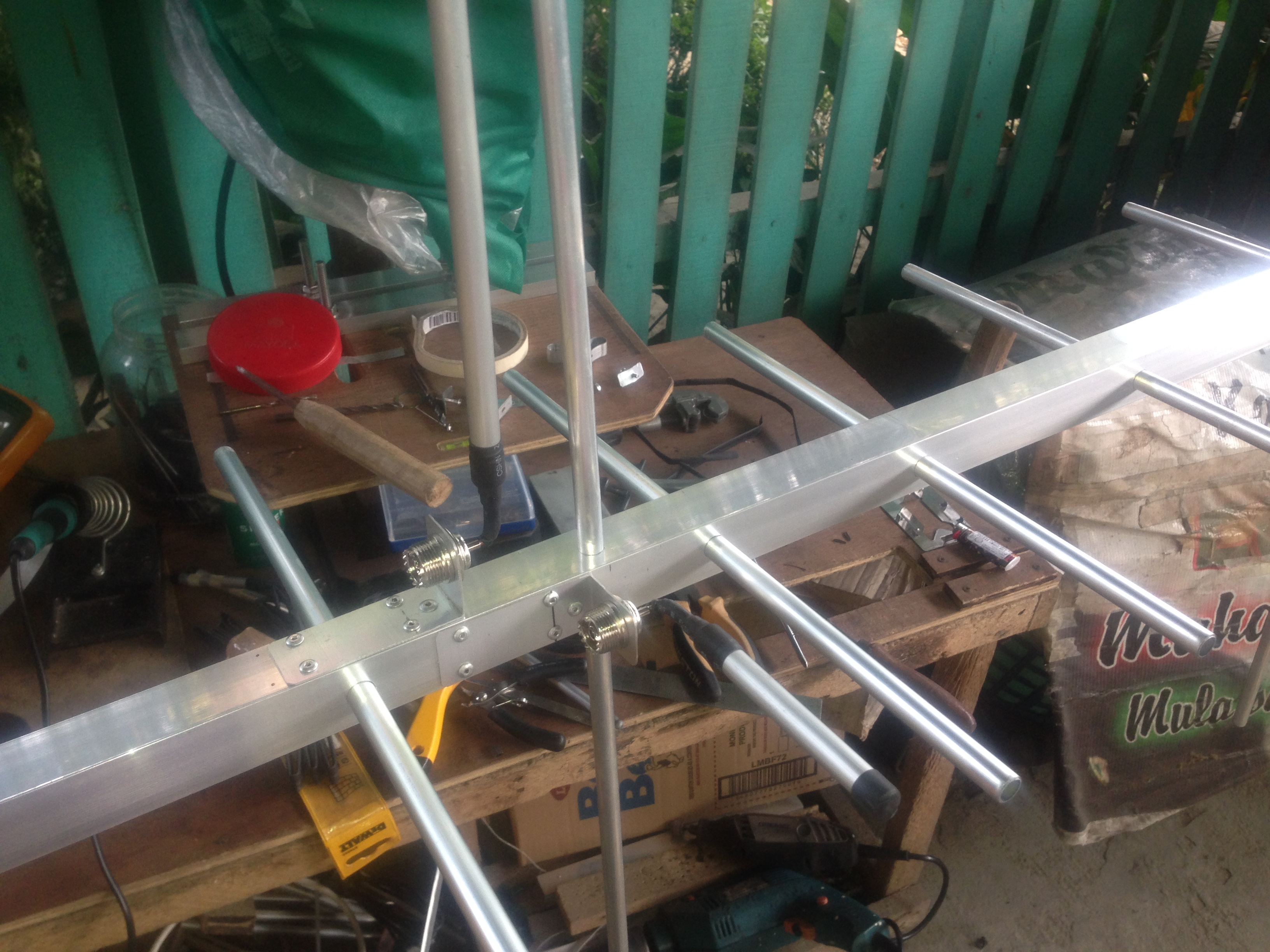
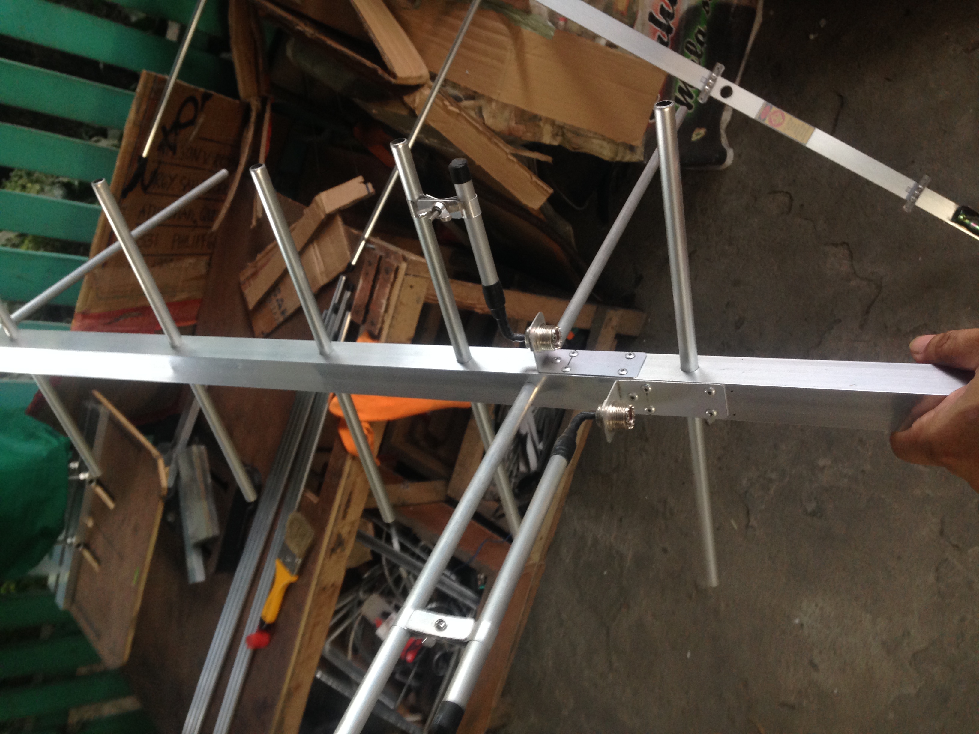
The bill of materials are similar to the inline version of this build except for the boom which uses 1 X 1 inch square boom.
Download the PDF document version here
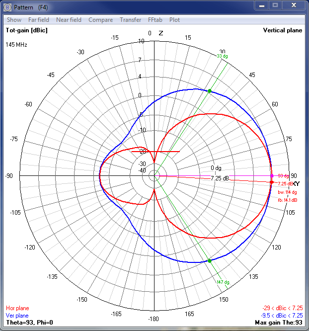
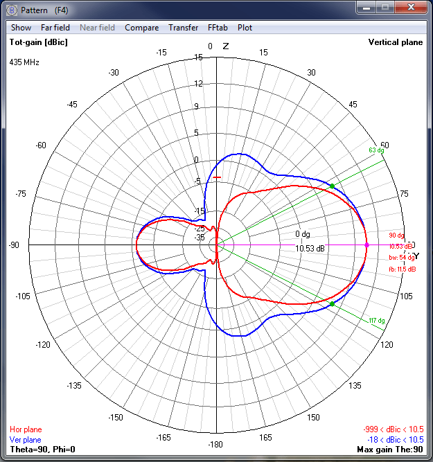
4NEC2 Antenna Data
4Nec2 data shows beamwidth, expected pattern and predicted gain.
Antenna analyzer measurements and actual video footage
Measurements are taken while holding the antenna and the analyzer since we know that yagi interacts with the actual measurements if it’s too close to an object. This is to simulate the actual use case when using the antenna aiming it to the satellites.
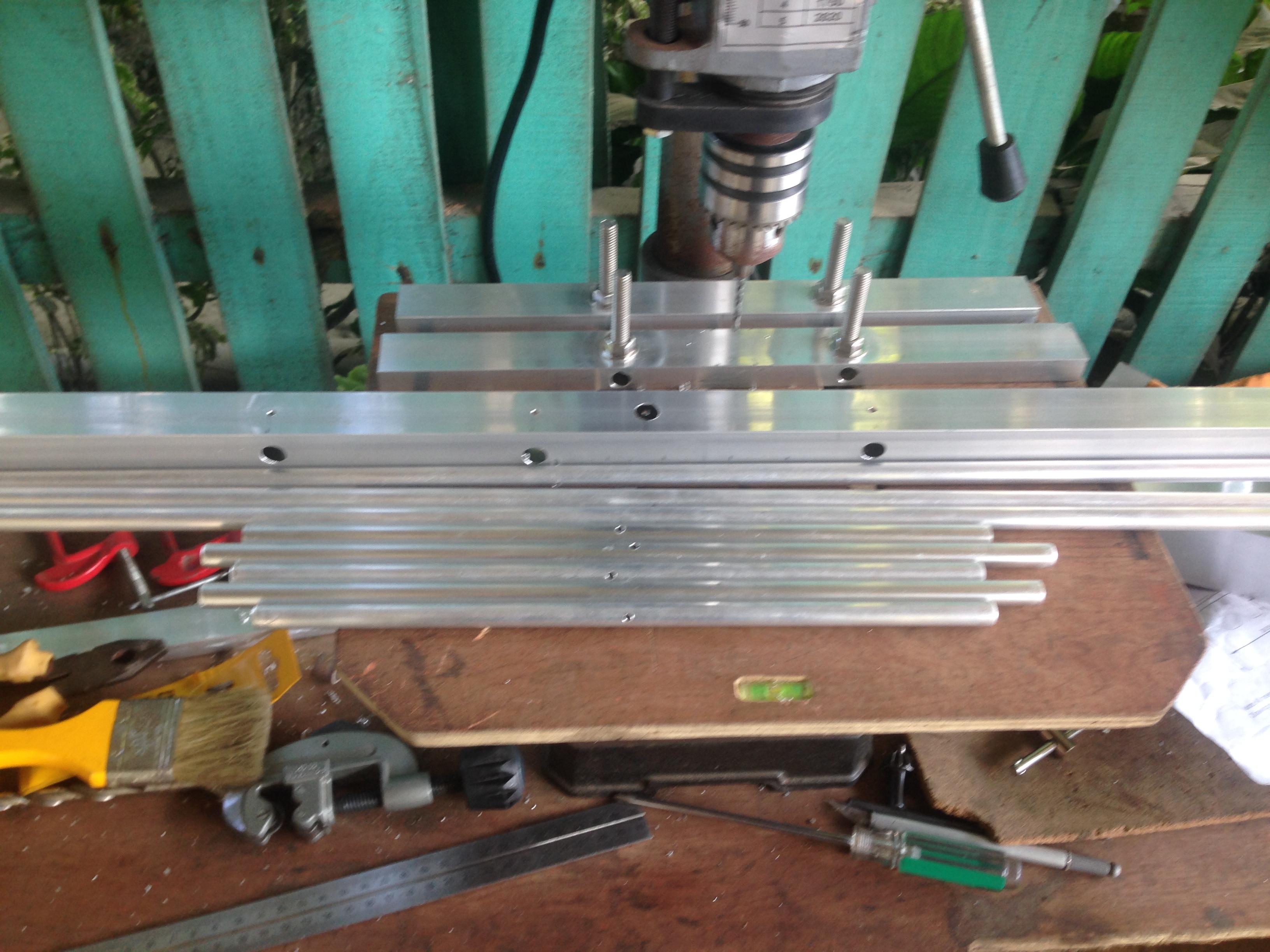
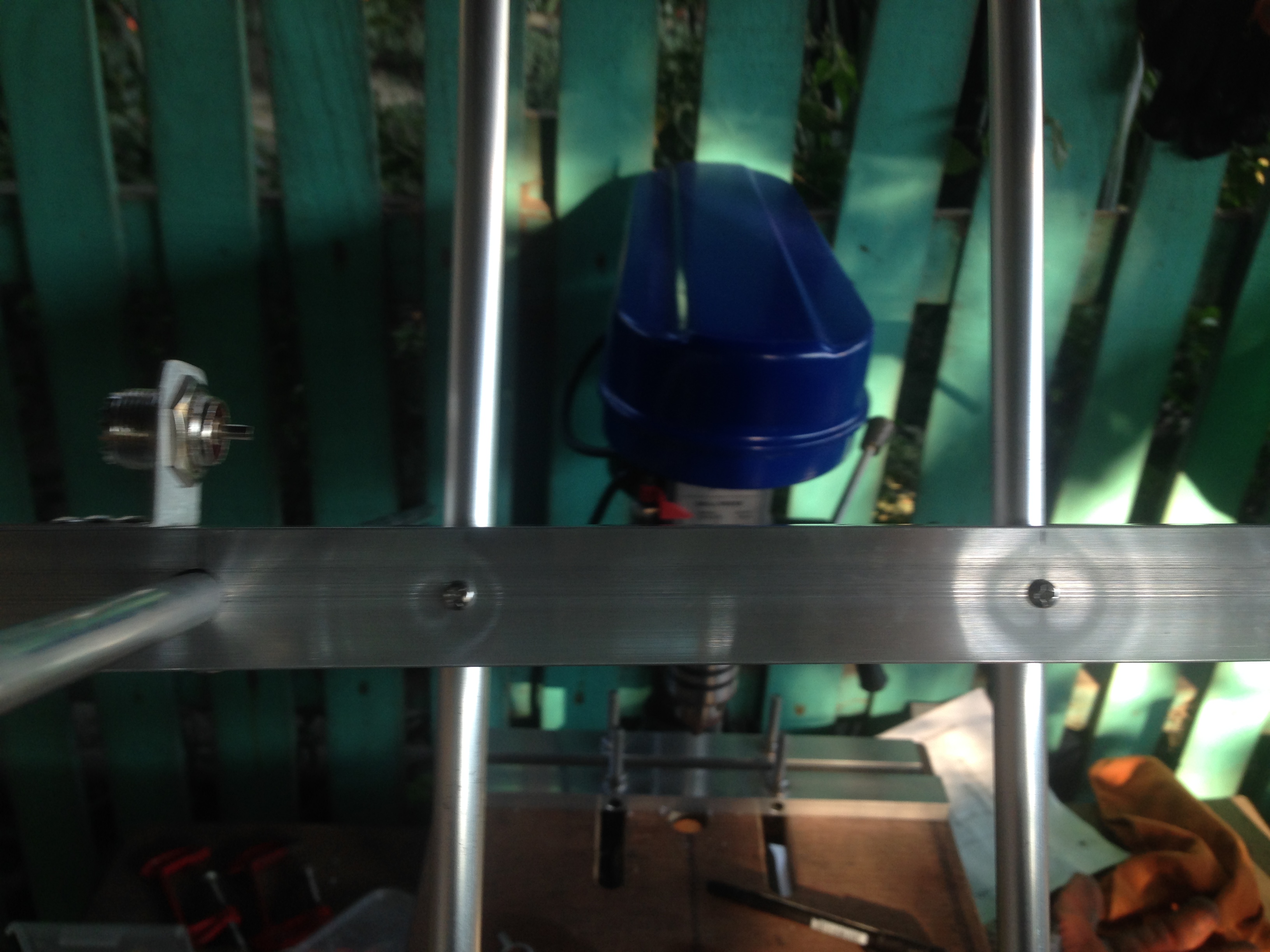
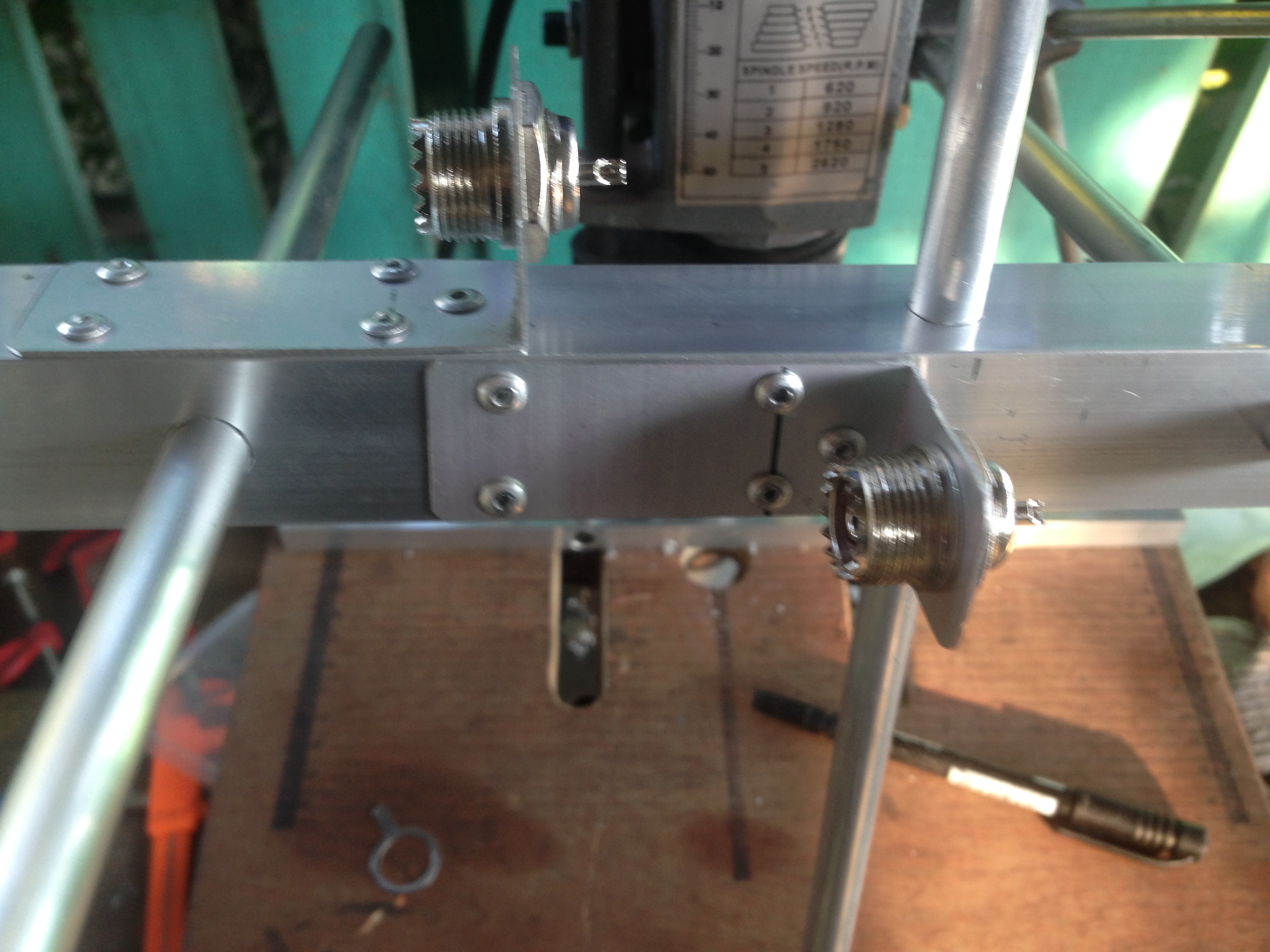
Actual build, measure, cut and drill
These are some photos I took when building the antenna.
Initial testing of this antenna
I initially test this antenna using a phasing harness of 75ohms at 1/4λ x 3 for the actual length of the harness considering the velocity factor of the coax. The final use case testing, uses 1/4λ x velocity factor for the actual length of the phasing harness.
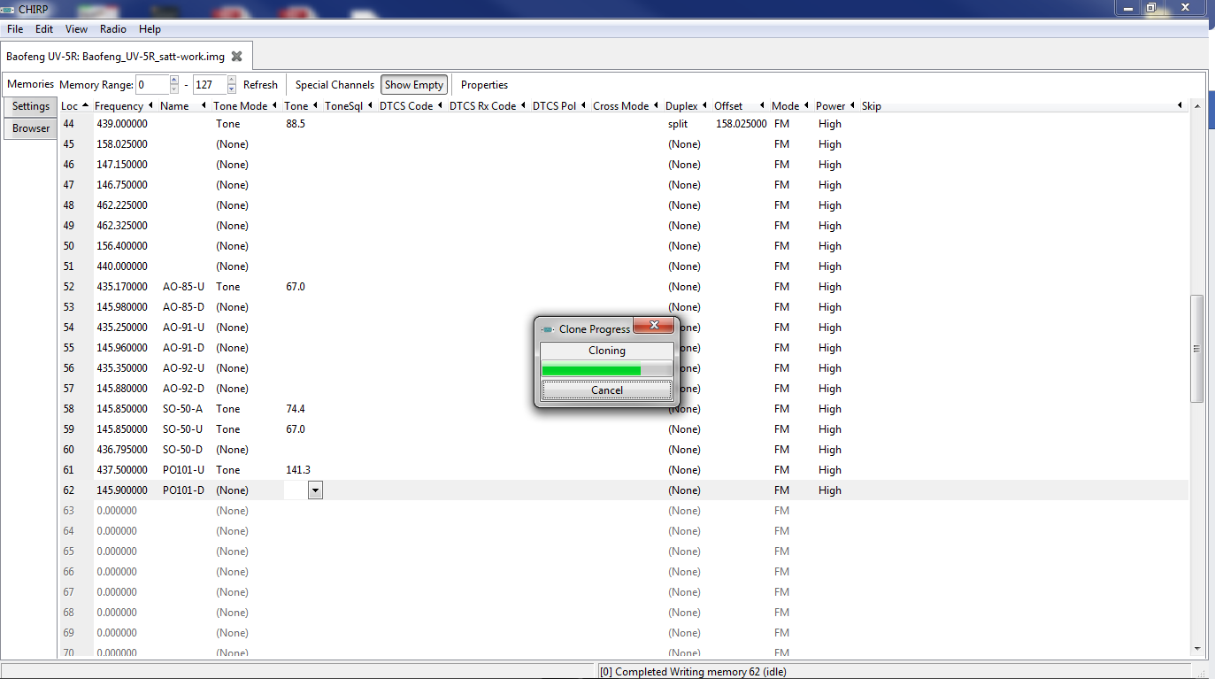
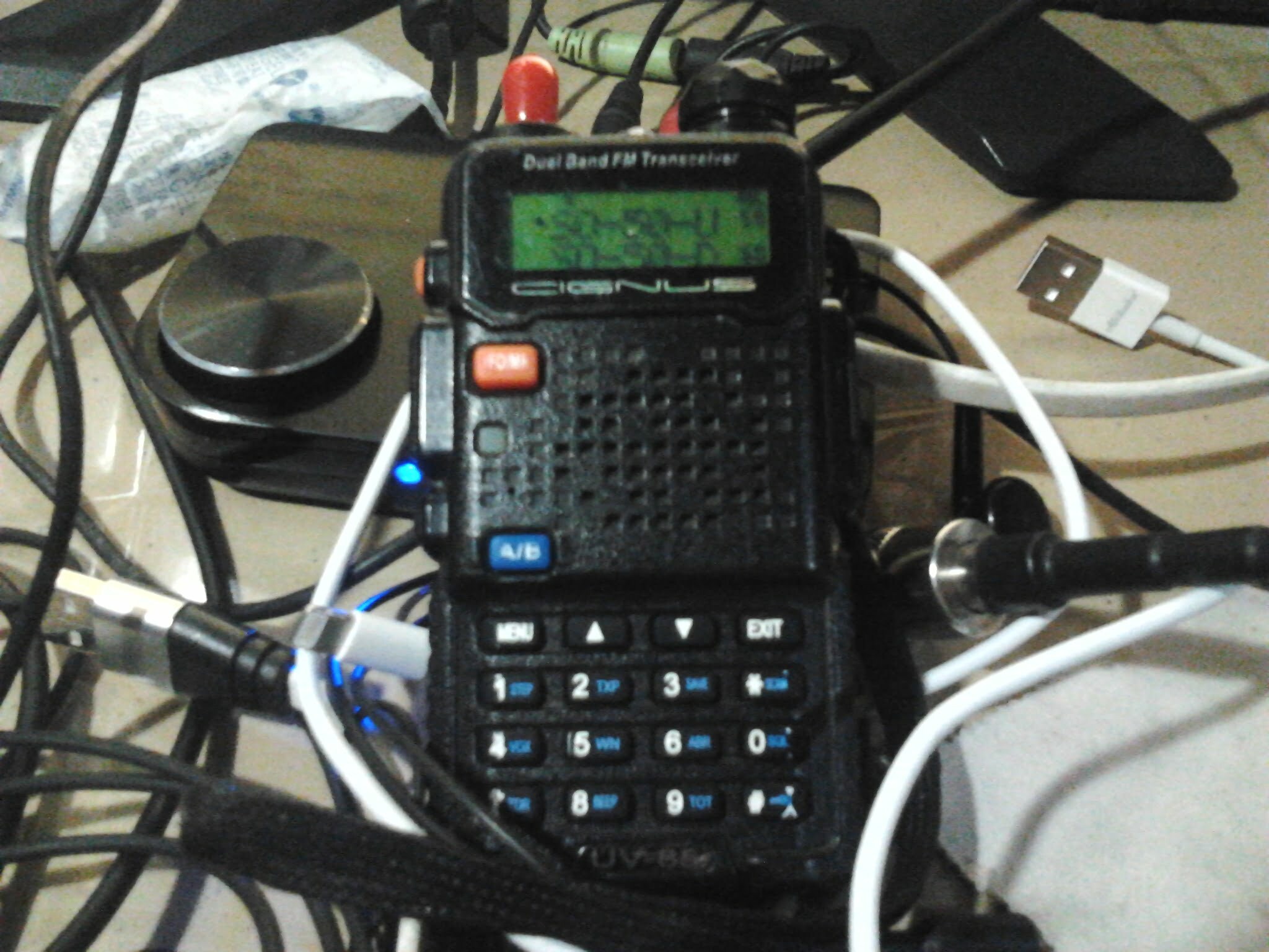
The fun part programming the radio before the hunt
Programming the radio with the satellite frequencies before the actual bird hunting. Since I work on a budget a Baofeng radio will suffice. I used a CIGNUS radio a rebranded radio that uses Baofeng internally ;). I encoded the frequency on the radio using CHIRP taking note of the CTCSS tone for each satellite and marking the channel name as name of the satellite and U for uplink D for downlink and A for arm to trigger some satellite timers before use.
Aside from programming the frequencies on your radio you also need a satellite tracker to predict the passes of the satellite you’re hunting. I uses Gpredict which works on both Windows and Linux machines, for Android you may use AmsatDroid Free version and tons of other satellites tracking apps on both Android and IOS.
The fun part really start when you begin the hunt and successfully received a very readable reception on your radio coupled with your homebrew antenna. If you’re not familiar with the actual satellite operations listen first until you feel comfortable pressing the PTT on your radio. Satellite resource hog are always frown upon so be courteous every time. Have fun!, and if you feel this will help someone feel free to share, thanks again!
4 replies on “Dualband 3×5 Cross Yagi 145Mhz – 435Mhz mounting and measurements”
Good day, sir. May I ask if sinama niyo ba sa computation ng element length yung size ng boom?
It’s up to you to redesign it if you like, a little adjustment to the elements due to boom the correction factor will not yield any measurable results on SWR. Unless you intend to use it on a high precision application then you may also need to consider all your available test equipment including the use of anechoic chamber to detect the changes in measurements due to boom correction.
If the aluminum pipe is 10mm instead of 9.5mm(3/8), will the distance between the pipes be the same? Thanks.
It will be the same as the measurements change is negligible on VHF frequency, effect is different of course if you are on higher frequency (i.e Ghz Band)