
Battery status indicator on the NanoVNA
Most available NanoVNA on the market has a working firmware that works from 50Khz to 900Mhz this version of the firmware doesn’t have the battery status indicator enabled. At the time of this writing there is already a version of firmware that can be flashed on the NanoVNA device to indicate battery status. This extends the frequency scanning to 1500Mhz although it may not be fully usable without a hardware upgrade. It contains experimental TDR function at this time originally released by edy555 on Github for NanoVNA the firmware release version is 0.2.2 inside the releases folder the files are provided as hex and bin need to be converted in DFU before you can use it in DfuSEdemo software unless you have a programmer for STM32 micro controller. I have converted the hex file to DFU and you may use it to flashed your device. If you don’t know what you are doing do it at your own risk the software is provided as is.
Download the files here. The original version of the files can be downloaded here https://github.com/ttrftech/NanoVNA/releases
Two steps to enable battery indicator
Step 1:
Add a missing diode on the board of NanoVNA. The diode is near the battery terminal marked ad D2 this was missing on NanoVNA board you need to add one. This was use to enable the actual status of the battery if it is fully charge or empty.
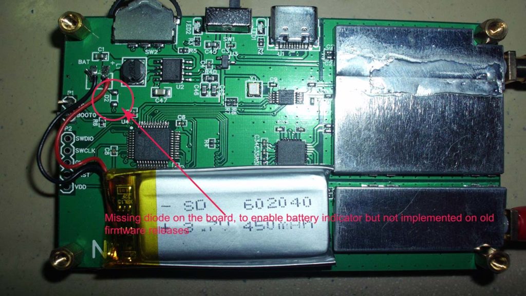
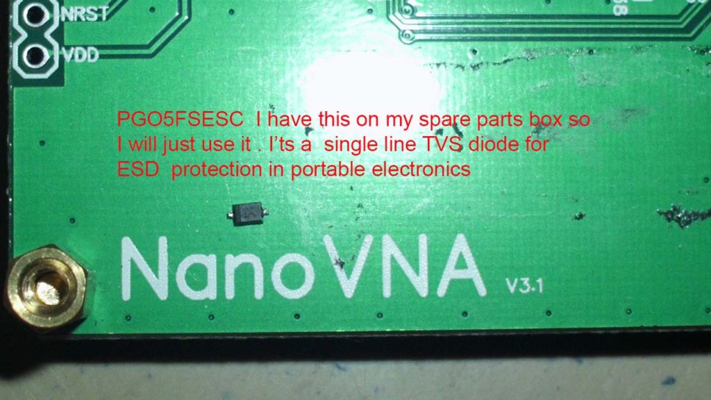
Use a suitable diode for this to mount on the NanoVNA pcb, edy555 recommends 1N4148WS or B5817WS or any small diode however I don’t have those ready so I looked into my tool box (junk box) and found PG05FSESC a TVS diode for ESD protection in portable electronics. Download PG05FSESC datasheet here.
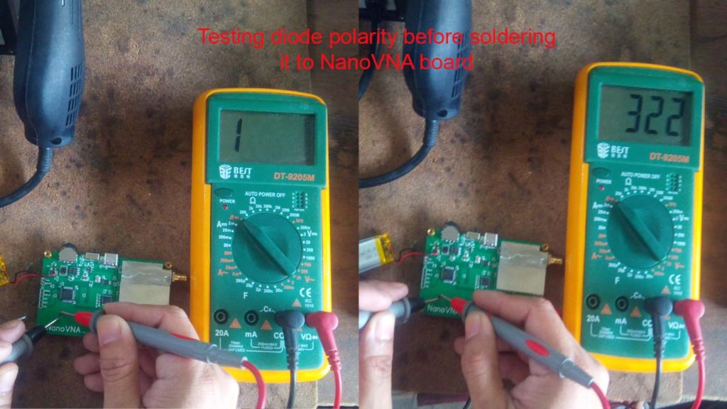
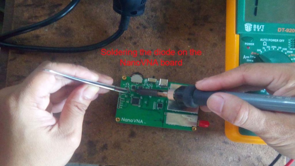
Test the polarity and solder the diode on the board.
Step 2:
Flashed the DFU firmware above to your NanoVNA device I have not include the actual flashing of the firmware here, but you may watch the instructions on how to do it from my youtube channel from this link: https://youtu.be/XBOTRcZI1qQ
When flashing the file you must first use the DMR-CLEAR_MEMORY_DFU.dfu file included from the downlink above before you flash the 0.2.2.dfu file.
After flashing the firmware you just need to re-calibrate your device and it’s ready again for normal use.
6 replies on “Enabling battery status indicator on NanoVNA”
Hi
Do you need to restart the VNA after applying DMR-CLEAR_MEMORY_DFU.dfu ? And with or without the BOOT0 strap ? Can you describe the detailed procedure please ?
Thanks and rgds
Hi Larry, you don’t need to restart the VNA after applying DMR-CLEAR_MEMORY_DFU.dfu, you can proceed in uploading the new DFU file then you can restart after successful flashing and recalibrate your device. Detailed procedure in uploading DFU is here >>> https://www.youtube.com/watch?v=XBOTRcZI1qQ
Tnx for your reply.
Regarding the diode, I guess the Anode is soldered on the pad near the battery wire, and the Cathode (usually marked with a white bar in SMD) is soldered on the other pad, right ?
Yes that is correct, I replied to your query on youtube, if that’s you?
Thank you for sharing this info!
I didn’t have an SMT diode so I used an axial 1N4148 and it works fine.
To use an axial diode you have to bend the leads 180 degrees into a C shape, as small as possible radius, with fine point tweezers, then clip them off so there’s about 2mm between the ends.
It should also be mentioned that unless you un-solder 1 battery lead you will be working “hot” so be careful to not short anything while positioning and soldering.
73, –KV5R
Thanks KV5R , yes better remove the battery before proceeding to avoid accidental shorts.