
QYT Modding
QYT KT8900 has good form factor that fits in the palm of your hand. It’s a dual band radio 2m/70cm that supports dual frequency monitoring has an acceptable receiver capability for the price, good audio performance (loud and crispy). Supports FM radio broadcast listening moreover it has a built in repeater function that will work in combination of another QYT KT8900 or pair it with QYT KT8900D by just enabling the function on the menu system and adding a repeater interface cable which can be built easily with spare LAN cable, RJ45 connectors and crimping tool.
If it’s not for the faulty heat sinking then probably this radio will work longer than expected rather than giving up the magic smoke of the RF finals too soon.
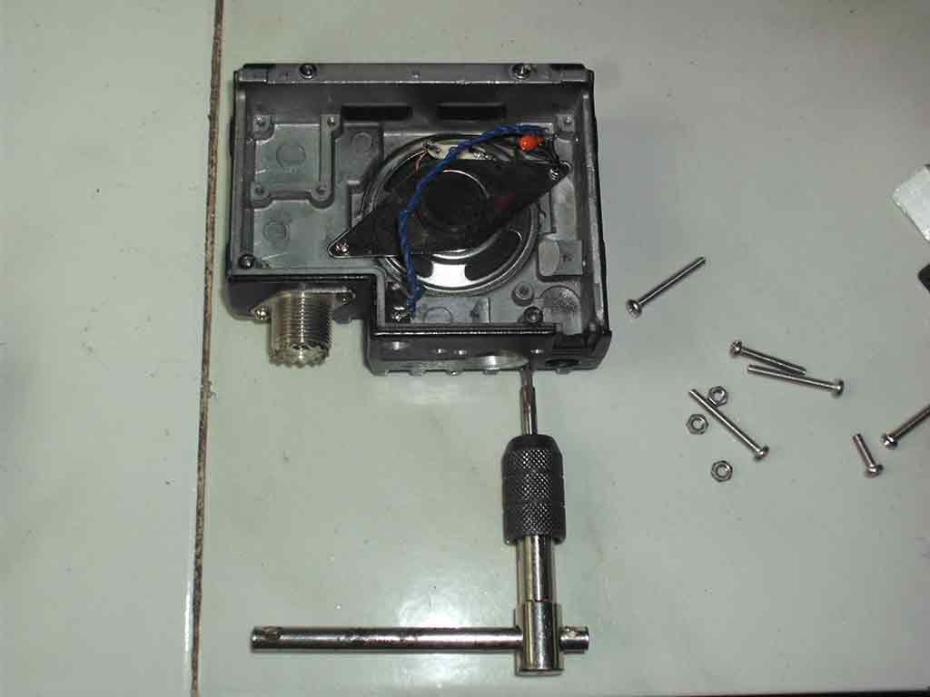
Preparing the RF finals removal and replacement
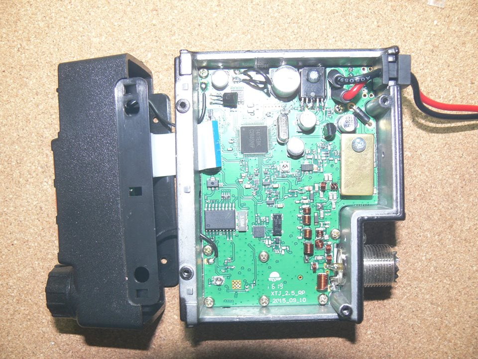
Disassembling the radio to replace the broken RF finals reveals that the screw holding the heat sink is loose just secured by a piece of copper strip inserted to the metal spacer to float the heat sink above the RF finals.
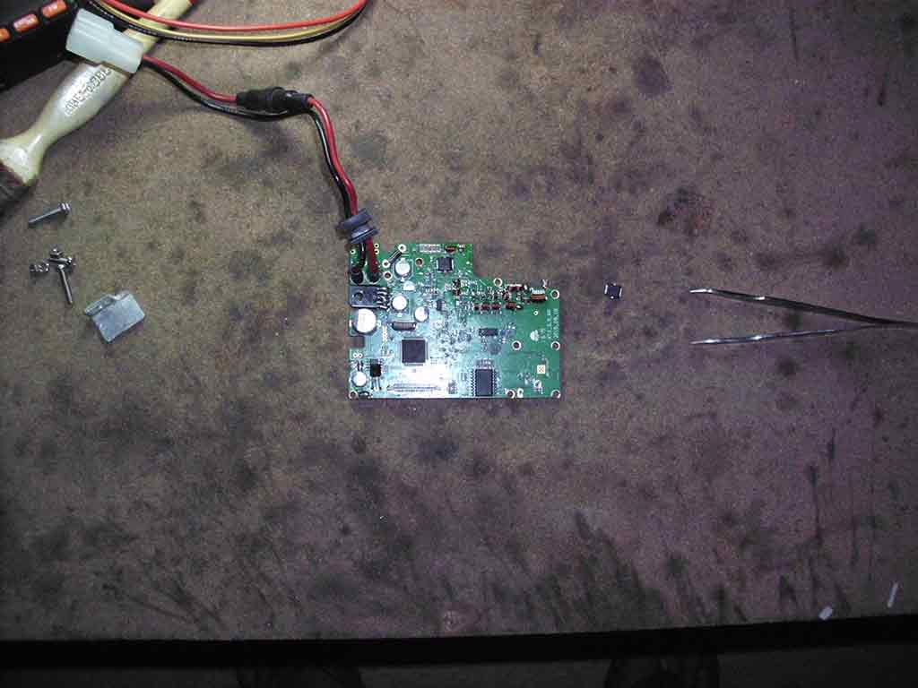
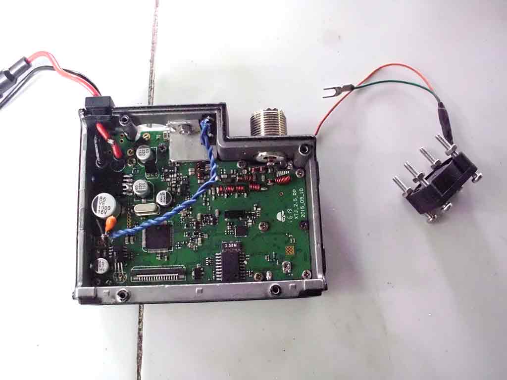
The radio board showing the QYT RF finals
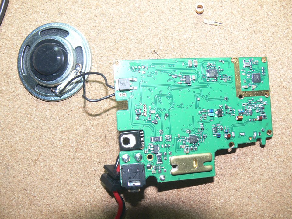
Replacing the RF finals is moderately easy provided you have the right tools a hot air rework station, solder flux, a pair of tweezers. The radio board backside reveals a slightly bigger heat sink which probably is intended to absorbed the heat more effectively by coupling it on the radio chassis, but without using a heat sink compound this also is not too effective to properly address the heat issue.
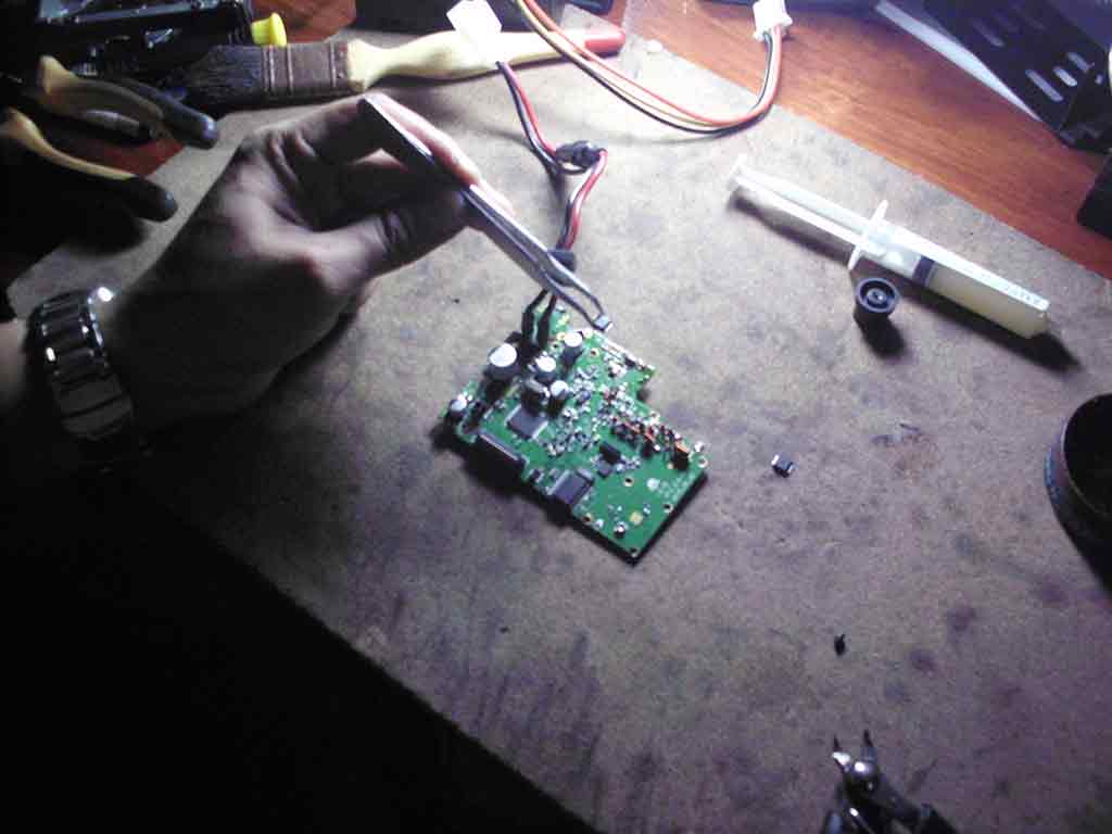
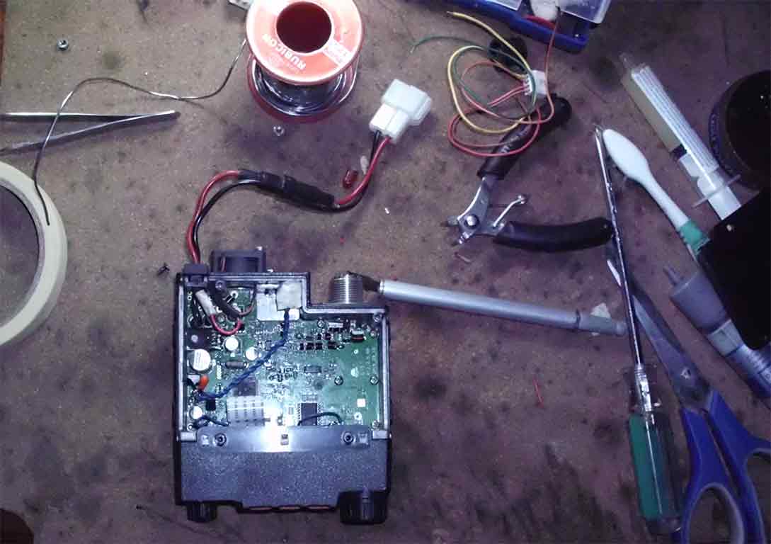
Time to replace the RF finals, apply the solder flux on the chip, heat the board just enough for the solder to melt at the bottom of the RF finals, remember that this is also attached to a copper heat sink below so heating it will take a little longer before you can see that a solder is flowing on the side of the finals. Once removed successfully replaced the finals with a new one. Good news for people living in the Philippines, the RF finals is now available by visiting your favorite electronics store in Gonzalo Puyat street in Sta. Cruz Manila price varies depending on the stores.
Replacing QYT RF Finals
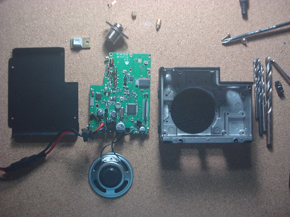
Preparing the fan modification on the radio chassis
Attaching the fan on the radio chassis requires a bit of drilling and tapping to hold the fan securely at the back of the chassis. For QYT KT8900 you can see at the back of the chassis that they somewhat prepared a fan mounting holes, but they didn’t pushed through with the plan. On later versions of this radio a fan is now attached to help in cooling the radio.
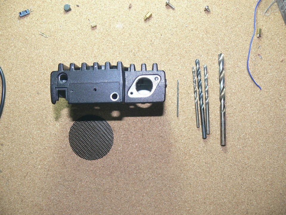
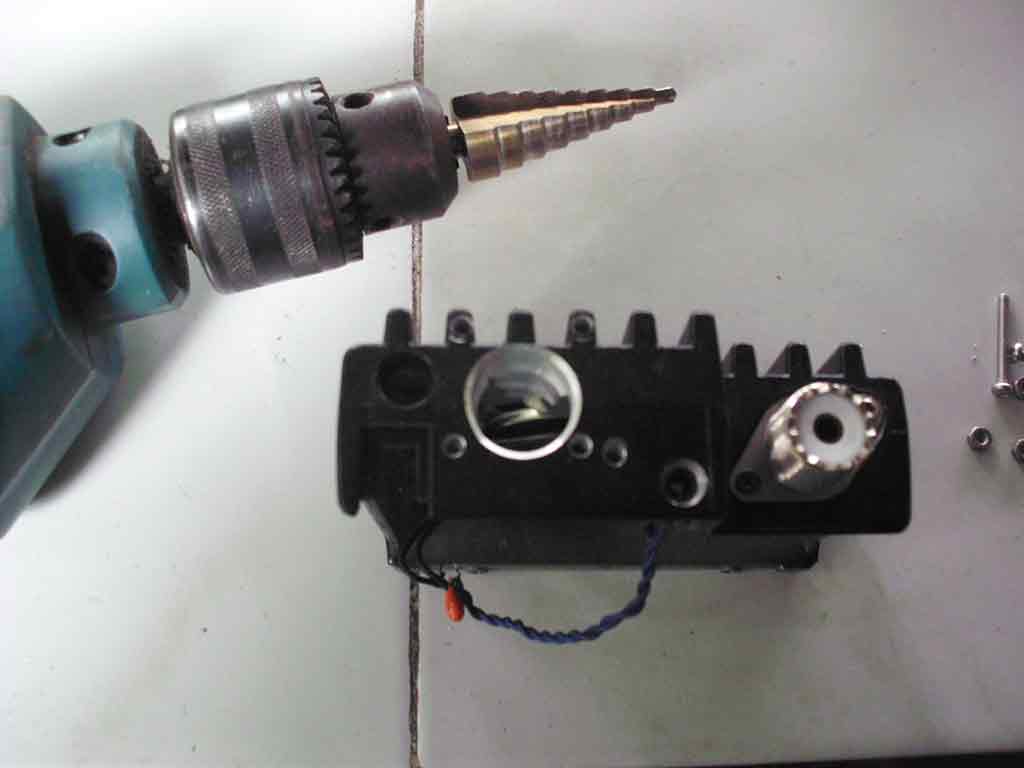
Drilling the fan mounting hole with a drill step bit.
Preparing the screws holder by tapping a thread.
Putting it back together.
Finally the finished modification applied to the radio.
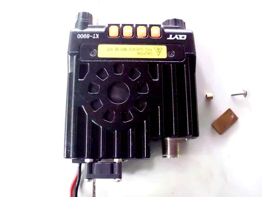
The final look and successful cooling fan modification.

18 replies on “Replacing broken RF finals QYT KT8900 and adding fan modification.”
good day sir… where can i buy the finals of qyt kt8900. mine is busted… 73 !!!
Raon in Manila, or try to contact BPC electronics on facebook.
How did you solder the chip to the board, ? AKI, solder the bottom of the device to the lower heat sink? Or did you
just solder the tabs. ???
You need a rework station to be able to remove and re solder the component to the radio board. Sometime people use heat blower to do that if you have one check out youtube for reference in doing it with a blower. Cheers!
that is how I got it off, but how do you get the solder under the device to put it back on, without cooking the device
Hi Stan, you need a solder flux to put it back on the board. If you managed to removed it using a blower you can put it back as well with the same tool but you have to put a solder flux on the board so that you will know if the solder is flowing at the back of component once the solder has reached the melting point the flux will help your solder to flow on the board and at the back of the component. Tip the component slightly with a twizzer to align it on the board and let it cool down. You will damaged the component by overheating usually a part of it will pop or smoke so you have to move the blower around the component and be alert when the solder starts to flow.
I got the lower heat sink off by using a micro flame, as the irons would not heat the heat sink up evenly, it came off clean
There seems to be too little room to feed solder in from the top side at the same time keeping the heat sink
at flow temp. Unless you have a sneaky way of getting it in there?
Usually you just need to be concerned on top, you don’t need to remove the bottom heat sink unless you want to change it. Applying little bit of solder and solder flux before placing the device on the same spot and reheating it will fix it in place. Cheers!
Found this very interesting application note for mounting these devices
http://cache.freescale.com/files/rf_if/doc/app_note/AN1907.pdf
that’s is a good reference but the important thing is when the solder starts to flow it is around 217°C, and you have 60 to 150 seconds to align it properly not exceeding peak body temperature < 260°C
So far this is what I have come up with.
Solder part in place from the top
Solder a small bridge copper stub to the bottom of the device extending through the PCB
Cut a notch in the lower heat sink, letting the bridge extend through the notch
Solder heat sink to the bridge
use a flame touch to re-solder the heat sink into place. Starting at it’s edges
My thought is I can work quickly and stay below too much heat for the device…??
that’s awesome, cheers to that basically this is what I’m using when doing board level repair.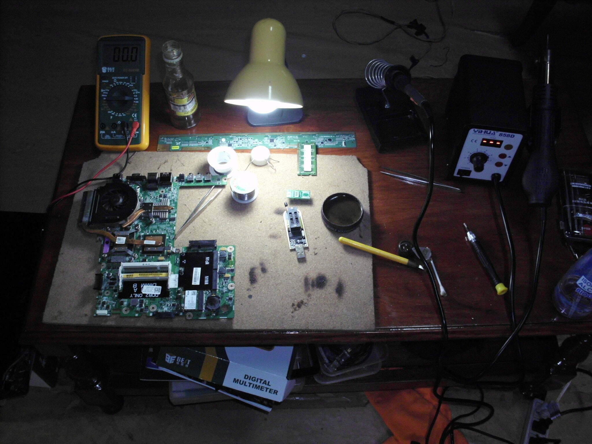
Good day po, Sir ibig sabihin po dapat pong palitan ang heat sink ng final po? Ano po ang magandang Ipakita na heat sink po para doon?
Salamat po sa tutugon.
Maraming salamat po
hi @Bon Consular – heatsink will definitely help in reducing heat directly applied to the radio finals thereby lengthening its usable lifetime (the bigger the better, its up to you on how you can fit it inside the case though), however it will eventually fail as it is overdriven to work at 25watts output power when the actual datasheet specifies that it is only a 6watts component see here: https://dw1zws.com/qyt-kt-8900-and-variants-rf-finals-aft05ms006nt1/
A 6 watt transistor is incorrect in this application. The correct final transistor is AFT09MS015NT1 available from Mouser for about $6. This is tested to 20W+ @870 MHz.
That is correct @Chuck the default RF finals supplied and installed on those radios are underrated when they first came out when I first created the article wayback 2018, now there are also 50W version of the RF finals which has similar mounting based on the original RF finals supplied but not sure if it would fit nicely or its a bit bigger will take a look if I get my hands on it. Thanks for commenting.
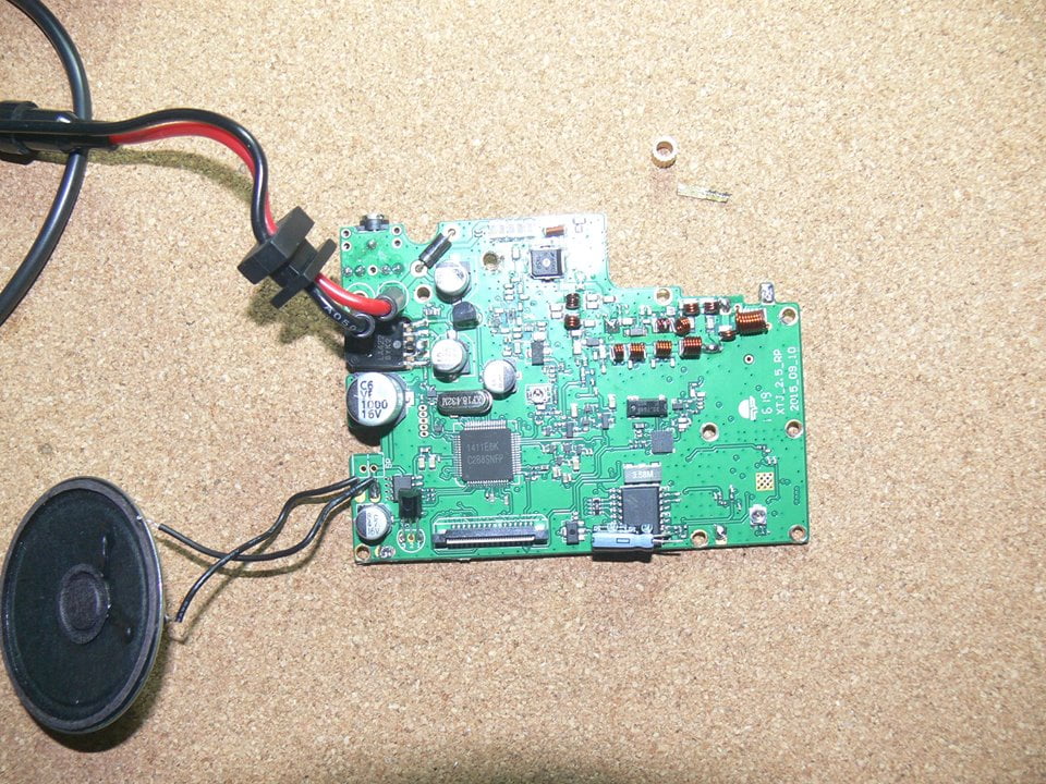
Interesting. For what it’s worth, I think the KT8900 radios are amazing. I’ve had mine for about 3 years of daily use in the car until the Final went out. It started to loose the CTCSS memory and when I checked the output, it was only transmitting at less than a watt of power and barely reaching 2 miles point to point. I was curious as to what the blue wire you installed on the board was?
It’s a filter capacitor from the audio IC, I added a modification for the audio out so I can plug a headset into it since the port at the back If I remember right was for programming interface only.