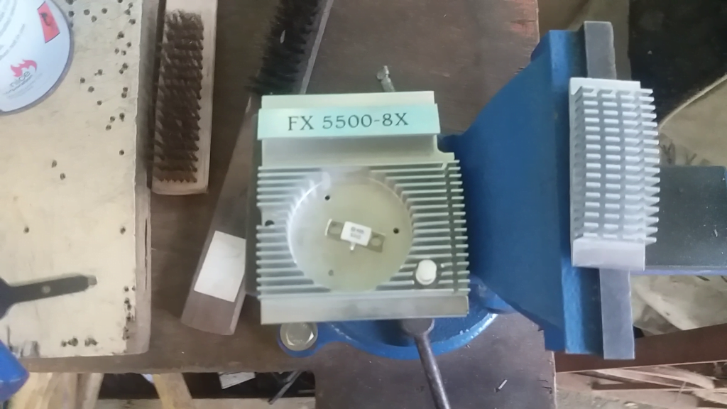
RF dummy load resistor can now be easily obtained from majority of popular online shops so obtaining one and building your own dummy load would not be a problem nowadays. So what is an RF dummy load?, a dummy load is a device used to simulate an electrical load, it is used to simulate an antenna in an RF system. A transceiver can be tested and configured without radiating a radio wave by using a dummy load. So if you are playing around with radio transceivers an RF load is a nice addition to your set of tools.
Materials
1. RF Resistor rated @ 50ohms/100Watts
2. 1×1 Aluminum square tube
3. Suitable aluminum heatsink (I’m repurposing a GPU heatsink from an old video card)
4. SO239 connector
5. Cutting tool
6. Soldering tools
7. NanoVNA, SWR meter and coaxial cables for testing.

For my build I cut a 2cm x 7cm aluminum heat sink from an old video card and attached the RF resistor on top of it and place it inside a 1 x 1 inch aluminum square tube. I cut a mounting hole on the heatsink and the aluminum square tube for mounting the heat sink and RF resistor. An SO239 feed point was used to connect the center tab of the RF resistor by soldering it directly on the center pin. The ground tab of the resistor is secured by a screw on the body of 1 x 1 aluminum tubing that serve as a holding case for my dummy load.
I tested the frequency response of the dummy load using the NanoVNA on both the 2m VHF and 70cm UHF amateur band with very good results. SWR on VHF is 1.07 and 1.2, 49 ohms to 57ohms impedance. The resulting impedance is negligible when using an analog SWR meter SX400.
The finished dummy load can easily handle 65watts transmitter power without over heating on short duration testing using my Yaesu 2900R transceiver. I also used a QYT KT8900D transceiver to test the power output of the radio at the UHF side.
Have a look on the video at my youtube channel for an overall build instruction video and testing.
