
Arduino Nano Technical Specifications
| Microcontroller | ATmega328P – 8 bit AVR family microcontroller |
|---|---|
| Operating Voltage | 5v |
| Recommended Input Voltage for Vin pin | 7-12v |
| Analog Input Pins | 6 (A0 – A5) |
| Digital I/O Pins | 14 (Out of which 6 provide PWM output) |
| DC Current on I/O Pins | 40 mA |
| DC Current on 3.3v Pin | 50 mA |
| Flash Memory | 32KB (2 KB is used for Boot loader) |
| SRAM | 2 KB |
| EEPROM | 1 KB |
| Frequency (Clock Speed) | 16 Mhz |
| Communication | IIC, SPI, USART |
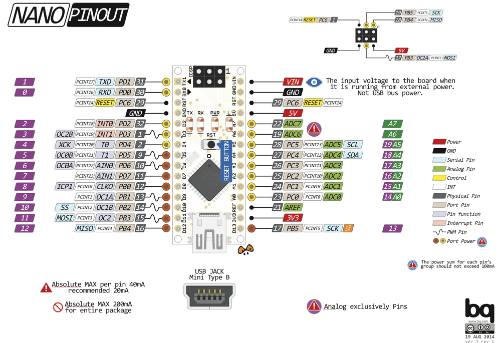
Arduino Nano Pin Configuration
| Pin Category | Pin Name | Details |
|---|---|---|
| Power | Vin, 3.3V, 5V, GND | Vin: Input voltage to Arduino when using an external power source (6-12V). 5V: Regulated power supply used to power microcontroller and other components on the board. 3.3V: 3.3V supply generated by on-board voltage regulator. Maximum current draw is 50mA. GND: Ground pins. |
| Reset | Reset | Resets the microcontroller |
| Analog Pins | A0 – A7 | Used to measure analog voltage in the range of 0-5V |
| Input/Output Pins | Digital Pins D0 – D13 | Can be used as input or output pins. 0V (low) and 5V (high) |
| Serial | Rx, Tx | Used to receive and transmit TTL serial data |
| External Interrupts | 2, 3 | To trigger an interrupt |
| PWM | 3, 5, 6, 9, 11 | Provides 8-bit PWM output |
| SPI | 10 (SS), 11 (MOSI), 12 (MISO) and 13 (SCK) | Used for SPI communication |
| Inbuilt LED | 13 | To turn on the inbuilt LED |
| IIC | A4 (SDA), A5 (SCA) | Used for TWI communication |
| AREF | AREF | To provide reference voltage for input voltage |